Do you have a question about the MATRIX TECHNOLOGY MPS-H-3 Series and is the answer not in the manual?
Detailed specifications and supplementary characteristics for the power supply models.
Recommended calibration frequency, cooling method, and environmental operating conditions.
Introduces the front and rear panels, detailing their components and layout with figures.
Guides users through initial checks, accessory verification, power connection, grounding, and power-on issues.
Explains how to set and adjust voltage and current levels for the power supply channels using knobs.
Covers turning the output ON/OFF and configuring series, parallel, or independent operating modes.
Details menu access for configuring parameter retention, buzzer, limits, OCP/OVP, CH3, and initialization.
Explains how to set and utilize Over Current Protection (OCP) and Over Voltage Protection (OVP).
Highlights safety warnings, attention notices, and explains safety symbols used in the manual.
Provides guidance on product repair, warranty terms, and customer responsibilities.
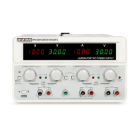
The MPS-H-3 series DC power supply is a new generation of high-quality linear DC power supply, designed for stable, reliable, and precise voltage and current output. This instrument features two independent channels for adjustable voltage and current, along with one fixed 5V/3A output. A key advantage of this series is its ability to simultaneously display output voltage and current for both main channels, offering a highly cost-effective solution for various laboratory and industrial applications.
The MPS-H-3 series DC power supply is engineered to provide a versatile and robust power source. Its primary function is to deliver regulated DC voltage and current to connected loads. The independent adjustability of voltage and current for each of the two main channels (CH1 and CH2) allows for flexible power delivery configurations. Additionally, a dedicated fixed 5V/3A output (CH3) caters to common low-voltage requirements.
A notable feature is the automatic conversion between stable voltage (CV) and stable current (CC) modes, ensuring that the power supply adapts to the load's demands while maintaining the set parameters. This intelligent behavior simplifies operation and protects connected devices.
The power supply incorporates a comprehensive set of protection functions to safeguard both the instrument and the connected load. These include Over Temperature Protection (OTP), Over Voltage Protection (OVP), and Over Current Protection (OCP). When an OVP or OCP event occurs, the affected channel will shut down, and a corresponding indicator will illuminate, alerting the user to the protective action. The CH3 channel also has its own overload indicator and protection mechanism, activating when the current exceeds approximately 3A and protecting the output if it surpasses 3.3A.
The instrument is designed with an infinite servo and intelligent fan system, which contributes to its high stability and reliability by efficiently managing internal temperatures. This ensures consistent performance even under varying load conditions.
Operating the MPS-H-3 series DC power supply is intuitive, thanks to its user-friendly front panel and clear display.
To set the voltage or current for CH1 or CH2, simply press the corresponding voltage/current knob. The display will show the setting position flashing, indicating that it's ready for adjustment. Turning the knob left or right will change the value. Pressing the knob again allows you to switch between different setting positions (e.g., tens, units, decimals). If no operation is performed for 5 seconds, the system automatically exits the setting state, saving the current value. The resolution for setting is 10mV for voltage and 1mA for current, allowing for fine-grained control.
Each main channel (CH1 and CH2) has an independent ON/OFF button ("OUTPUT1" for CH1, "OUTPUT2" for CH2) to control its output status. This allows users to enable or disable power to specific loads without affecting other channels. In series or parallel modes, the "OUTPUT2" button acts as the master control for the combined output, while "OUTPUT1" becomes inactive.
The MPS-H-3 series offers a convenient one-key series and parallel function. A light press of the dedicated "one-key series/parallel/function menu button" on the left side of the front panel will cycle through independent, series, and parallel working states.
The power supply includes a voltage and current preset function, allowing users to store and recall frequently used settings. This enhances efficiency and repeatability in experimental setups.
To prevent accidental over-voltage or over-current conditions, the MPS-H-3 series features a voltage and current range limit function. This allows users to define upper and lower operational boundaries for each channel, adding an extra layer of safety.
Long pressing the "one-key series/parallel/function menu button" enters the menu setting mode, offering several configurable options:
Long pressing the voltage/current adjustment knob allows access to the OVP/OCP function settings.
The MPS-H-3 series DC power supply is designed for long-term reliability and ease of maintenance.
The manufacturer recommends a calibration frequency of once per year to ensure continued accuracy and performance.
In case of a power failure to start, checking and potentially replacing the fuse is a straightforward process. The fuse is located under a small plastic cover on the rear panel, near the power input socket. Users can open this cover with a screwdriver and replace the fuse with one of the same specification.
Upon power-on, the power supply performs a system self-test before entering standby mode, ensuring all internal components are functioning correctly. The instrument also features an initialization function. By long-pressing the "one-key series/parallel/function menu button" while turning on the power, the power supply will initialize its function menu. After successful initialization, indicated by three "di-di-di" beeps, the settings will revert to specific default values, such as power-on parameter retention ON, output status OFF at power-on, buzzer sound ON, and all voltage and current limits set to their minimum or maximum ratings for the specific model. This provides a quick way to reset the device to a known state.
The manual emphasizes safety precautions, including warnings about high voltage and the importance of proper grounding. Users are advised not to install substitute parts or perform unauthorized modifications. For repairs, the instrument should be sent to the company's designated maintenance department to ensure safety and proper functioning. The company provides a three-year quality guarantee for materials and manufacturing from the date of shipment, covering construction defects or part failures under normal use. However, the warranty does not cover damage resulting from user modifications, improper use, or external factors like natural disasters.
| Input Voltage | 85-264VAC |
|---|---|
| Input Frequency | 47-63 Hz |
| Safety Standards | UL/cUL, TUV, CE |
| Output Power | 75 W |
| Protection Features | Over Voltage, Over Current, Short Circuit |
| Cooling Method | Convection |