19
NORM:TheNORMswitchprovidesnormaltriggeredsweepoperation.Thesweepremainsatrestuntiltheselectedtriggersource
signalcrossesthethresholdlevelsetbytheTRIGLEVELcontrol.Thetriggercausesonesweeptobegenerated,afterwhich
sweepagainremainsatrestuntiltriggered.IntheNORMposition,therewillbenotraceunlessanadequatetriggersignalis
present.IntheALTmodeofdualtraceoperationwithNORMsweepselected,therewillbetraceunlessbothchannel1and2
signalsareadequatefortriggering.
TV-V:SettingtheMODEswitchtotheTV-Vpositionpermitsselectionofverticalsyncpulsesforsweeptriggeringwhen
viewingcompositevideowaveforms.Verticalsyncpulsesareselectedastriggertopermitviewingofverticalfields
andframesofvideo.Asweeptimeof2ms/DIVisappropriateforviewingfieldsofvideoand5ms/DIVforcomplete
frames(twointerlacedfields)ofvideo.
TVH:SettingtheMODEswitchtotheTV-Hpositionpermitsselectionofhorizontalsyncpulsesforsweeptriggeringwhen
viewingcompositevideowaveforms.Horizontalsyncpulsesareselectedastriggertopermitviewingofhorizontalfieldsof
video.Asweeptimeofabout10us/DIVisappropriatefordisplayinglinesofvideo.TheSWPVARcontrolcanbesetto
displaytheexactnumberofwaveformsdesired.
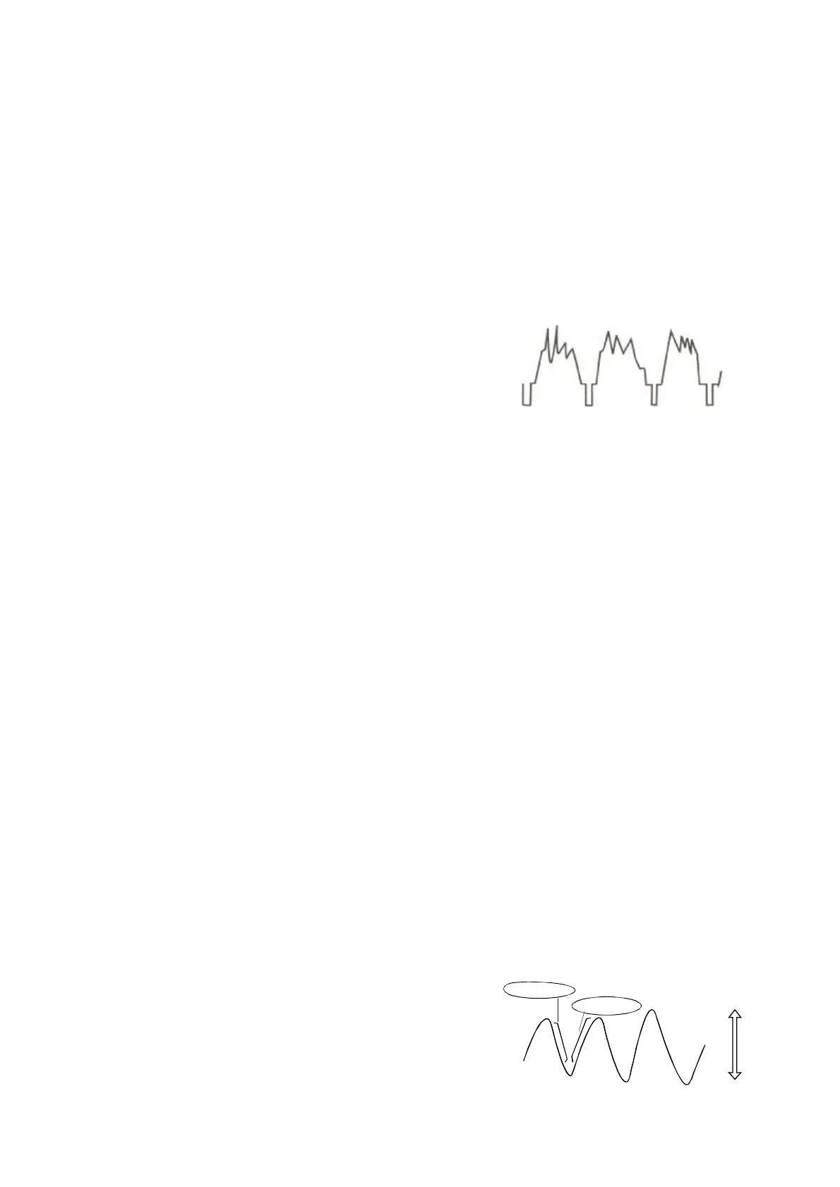
Thisoscilloscopesynchronizeswithonly(-)polarity,thatis,thesyncpulsesarenegativeandthevideoispositiveasshownin
Figure4-6.
(2)FunctionsofSOURCEswitch:
Thedisplayedsignalitselforatriggersignalwhichhasatime
relationshipwiththedisplayedsignalisrequiredtobeappliedtothe
triggercircuittodisplayastationarysignalontheCRTscreen.
TheSOURCEswitchisusedforselectingsuchatriggeringsource
CHl/CH2:Theinternaltriggermethodwhichisusedmostcommonly.Thesignalappliedtotheverticalinputterminalis
branchedofffromthepreamplifierandisfedtothetriggercircuitthroughtheVERTMODEswitch.Sincethetriggering
signalisthemeasuredsignalitself,astablewaveformcanbereadilydisplayedontheCRTscreen.WhenintheDUALor
ADDoperation,thesignalselectedbytheSOURCEswitchisusedasthetriggeringsourcesigna1.
-
.
Figure4-6
20
Line:TheACpowerlinefrequencysignalisusedasthetriggeringsignal.Thismethodiseffectivewhenthemeasured
signalhasarelationshipwiththeAClinefrequency,especiallyformeasurementsoflowlevelACnoiseofaudio
equipment,thyristorcircuits,etc.
EXT:Thesweepistriggeredwithanexternalsignalappliedtotheexternaltriggerinputterminal.Anexternalsignal
whichhasaperiodicrelationshipwithrespecttothemeasuredsignalisused.Sincethemeasuredsignalisnotused
asthetriggeringsignal,thewaveformscanbedisplayedmoreindependentthanthemeasuredsignal.
(3)FunctionsofTRIGLEVELcontrolandSLOPEswitch:
Asweeptriggerisdevelopedwhenthetriggersourcesignalcrossesapresetthresholdlevel.RotationoftheTRIGLEVEL
controlvariesthethresholdlevel.Inthe"+"direction,thetriggeringthresholdshiftstoamorepositivevalue,andinthe"-"
direction,thetriggeringthresholdshiftstoamorenegativevalue.Whenthecontroliscentered,thethresholdlevelissetat
theapproximateaverageofthesignalusedasthetriggeringsource.
TheTRIGLEVELcontroladjuststhestartofthesweeptoalmostanydesiredpointonawaveform.Onsinewavesignals,
thephaseatwhichsweepbeginsisvariable.NotethatiftheTRIGLEVELcontrolisrotatedtowarditsextreme+or-setting,
nosweepwillbedevelopedintheNORMtriggermodebecausethetriggeringthresholdexceedsthepeakamplitudeofthe
syncsignal.
WhentheTRIGSLOPEswitchissettothe(+)position(up),thesweepisdevelopedfromthetriggersourcewaveformasit
crossesthethresholdlevelinapositive-goingdirection.WhentheTRIGSLOPEcontrolissettothe(-)position(down),a
sweeptriggerisdevelopedfromthetriggersourcewaveformasitcrossesthethresholdlevelinanegative-goingdirection.
Thisswitchselectstheslope(polarity)triggeringsignalasshowninFigure4-7.
TRIGLEVELLOCK
Adjustlevel(28)tofullyclockwise,thetriggeringlevelislockedatafixed
value,andstabletriggeringismadewithoutrequiringleveladjustment.
ThisTriggerlevellockfunctioniseffectivewhenthesignalamplitude
onthescreenortheinputvoltageoftheexternaltriggeringsignaliswithin
thefollowingrange:
620B/5620NF/620BF/620R:640B/650B/640BF/650BF/640R/650R:
50Hz--2MHz:1.0DIV50Hz--20MHz:1.5DIV
2MHz--20MHz:2DIV20MHz--50MHz:3DIV
≥≥
≥≥
Slope
"-"Range
Figure4-7
Level
+
-
Slope"+"Range