8
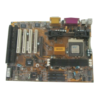
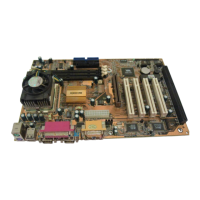
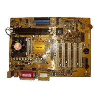
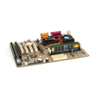
Key to Mainboard Components
Component Description
ISA1,2 2 x 8/16-bit ISA expansion slots
AGP1 AGP graphics adapter slot
PCI 1,2,3,4 4 x 32-bit PCI expansion slots
SOCKET PGA370 Processor socket for PPGA Celeron processor
SLOT1 Slot for Pentium-II/III processor or SEPP Celeron processor
DIMM1,2,3 Slots for 168-pin memory modules
FDD1 Connector for floppy disk drives
IDE1, IDE2 Primary and secondary IDE channels
ATX1 Connector for ATX power supply
SIR1 Connector for optional IR port
PANEL Panel connector for switches and indicators
CPUFAN1 Power connector for CPU cooling fan
CASEFAN1 Power connector for case cooling fan
WOM1 Connector for modem wake up
WOL1 Connector for LAN wake up
SPDIF1 SPDIF In/out connector (24-bit digital audio interface)
SIDEBAND1 SB-Link connector for Sound Blaster audio card
CD1 Audio connector for optional CD-ROM drive
CD2 Auxiliary audio connector for optional CD-ROM drive
J1 Connector for fax/modem Adapter Card
J2 Head for Indicator lamp for Suspend to RAM
JP1 Clear CMOS memory jumper
JP2 Keyboard power on jumper
JP4 System Bus Frequency Selector
JP7 Flash BIOS enable/disable jumper
LED1 Suspension indicator
*J2
This head is for Indicator lamp for Green mode. This red indicator lamp
turns on if your computer has been suspended to RAM. In a suspend to
RAM, the system turns off most of the power-consuming components
except for the 3.3V required to refresh the memory. If the indicator lamp
is turned on, it warns you that the computer is suspended to RAM and a
refresh current is passing through the memory modules. You should not
attempt to remove or install memory modules when the indicator lamp is
turned on.
 Loading...