Do you have a question about the MATSONIC MS7157C and is the answer not in the manual?
Details FCC compliance rules for Class B digital devices, including interference mitigation measures.
States compliance with FCC rules and outlines the conditions under which operation is permitted.
Confirms compliance of the Class B digital apparatus with Canadian Interference-causing Equipment Regulations.
Protects the publication's content, including photographs, illustrations, and software, under international copyright laws.
States that information is subject to change without notice and disclaims warranties regarding content accuracy or fitness.
Lists registered trademarks of various companies for hardware and software components mentioned in the manual.
Congratulates the user on purchasing the MS7157C mainboard and highlights its key features and capabilities.
Explains the manual's organization and provides an overview of the contents of each chapter.
Lists standard and optional components that are shipped with the mainboard for verification.
Provides advice on handling components, avoiding static electricity, and cautions against overclocking for reliability.
Provides a general overview of the mainboard's features, including chipset and processor support.
Details the supported processors, including their specifications and socket compatibility.
Describes the mainboard's three DIMM slots for installing SDRAM memory modules and their capacity.
Details the VIA VT82C694X/VT82C596B chipset, highlighting its features and performance benefits.
Describes the integrated CMI 8738 PCI audio solution, including its features and compatibility.
Describes the integrated fax/modem connector and its capabilities for communication.
Details the available AGP, PCI, and ISA expansion slots for adding functionality.
Lists the integrated I/O ports and interfaces on the mainboard, such as USB, serial, and parallel ports.
Explains the integrated hardware monitoring system for tracking system parameters like temperature and fan speeds.
Describes how to configure the system to power on using a keyboard-typed password or hot keys.
Discusses the Award BIOS for system configuration, including CPU parameters and power management settings.
Provides an overview of the installation procedure steps for building a working system.
Offers a quick guide to jumper settings on the mainboard for initial configuration.
Advises on precautions before installing the mainboard, focusing on static electricity avoidance and case selection.
Explains the concept of jumpers and provides illustrations on how to set them on the mainboard.
Guides on selecting a suitable case and preparing the mainboard for physical installation.
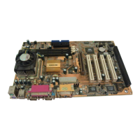
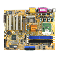
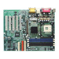
Illustrates and keys the mainboard components to help users identify them.
Provides a detailed list of mainboard components and their corresponding descriptions.
Shows a diagram illustrating the layout of the mainboard's external I/O ports.
Explains the function of each specific I/O port visible on the mainboard's rear panel.
Ensures all mainboard jumpers are configured correctly according to installation requirements.
Details the JP1 jumper's function for clearing CMOS memory data and system setup settings.
Explains the JP2 jumper for enabling the system to power on via keyboard password or hot keys.
Details the JP7 jumper for enabling the Suspend-to-RAM feature for power saving.
Explains the JP8 jumper for enabling or disabling Flash BIOS protection to prevent overwrites.
Details the JP9 jumper for setting the system bus frequency to 100 MHz.
Details the JP10 jumper for setting the system bus frequency to 133 MHz.
Explains jumper settings for selecting the processor type (Celeron or Joshua) for the Socket-370.
Covers the JP15 jumper for automatic (BIOS) or manual CPU core voltage and multiplier ratio configuration.
Details the VID jumpers for manually setting the CPU core voltage according to processor requirements.
Explains the BF jumpers for manually setting the system bus multiplier ratio for CPU clock speed.
Guides on physically installing the mainboard into the computer case using mounting brackets and screws.
Instructions for connecting the mainboard's power, chassis fan, and case panel connectors.
Instructions for connecting the ATX power cable from the power supply unit to the mainboard.
Instructions for connecting the chassis cooling fan cable to the mainboard's fan power supply connector.
Guides on connecting case switches and indicators to the mainboard's PANEL1 connector.
Guides on installing essential hardware components like processor, memory, and drives.
Guides on selecting and installing the processor, considering performance requirements and price.
Details supported Socket-370 processors, including Intel Celeron, Cyrix Joshua, and Intel Coppermine.
Step-by-step instructions for installing a Socket-370 processor, including socket and lever operations.
Instructions for installing 168-pin 3.3V DIMM memory modules, including slot keying and latching.
Guides on installing IDE devices like hard disk drives and CD-ROM drives using IDE channels.
Explains the mainboard's IDE channels, ribbon cables, and the concept of master/slave device configuration.
Step-by-step guide for installing a hard disk drive, including IDE cable and power connections.
Step-by-step guide for installing a CD-ROM drive, including IDE cable, power, and audio connections.
Guides on installing the floppy diskette drive, including data and power cable connections.
Instructions for installing expansion cards into AGP, PCI, and ISA slots to add functionality.
Describes the AGP slot and its use for installing an AGP graphics adapter.
Describes the PCI slots and their use for installing 32-bit PCI expansion cards.
Describes the ISA slot and its use for installing legacy 8/16-bit ISA expansion cards.
Options for add-in cards such as Wake on LAN (WOL1) and Wake on Modem (WOM1).
Explains the Wake On LAN feature using the WOL1 connector for network adapter wake-up.
Explains the Wake On Modem feature using the WOM1 connector for modem wake-up.
Instructions for installing optional features like fax/modem cards and IR ports.
Instructions for installing the optional fax/modem card onto the J1 connector.
Details connecting the optional IR port and potential resource conflicts with serial ports.
Guides on connecting external peripheral devices to the mainboard's I/O ports.
Explains the PS/2 ports for keyboard and mouse connection.
Explains the function of the parallel port (LPT1) for printers and other devices.
Details the game/MIDI port and the three audio jacks for line out, line in, and microphone.
Explains the COM2 serial port, identified as COM2/4, for serial devices.
Explains the COM1 serial port, identified as COM1/3, for serial devices.
Explains the Universal Serial Bus ports for connecting USB devices.
Explains the BIOS setup utility, its purpose, and how it stores system configuration data.
Details the procedure to enter the BIOS setup utility by pressing the DEL key during system startup.
Describes navigation methods within the setup utility, including cursor keys, Enter, and function keys.
Displays basic system information configurable in BIOS, such as date, time, and IDE devices.
Allows modification of advanced system settings without causing fatal errors.
Provides a step-by-step guide for updating the system BIOS using a flash utility.
Explains how to set the system's date and time, which can be updated automatically by Windows.
Covers configuration for IDE devices like hard drives and CD-ROMs on primary and secondary channels.
Utility within BIOS setup for automatic detection and configuration of IDE hard drives.
Setting IDE devices as Master or Slave on the IDE channels for proper operation.
Defines special access modes for IDE hard disks, such as LBA addressing.
Defines the characteristics of attached diskette drives, supporting one or two drives.
Sets the system's video mode; typically left at default for the onboard VGA.
Configures POST error handling, selecting which errors are sufficient to halt the system.
Provides protection against viruses attempting to write to the boot sector and partition table.
Enables monitoring of the Real Time Clock for Y2K compliance to prevent data corruption.
Enables or disables the mainboard's Reset button connector.
Controls the CPU's Level 1 internal cache for performance optimization.
Controls the CPU's Level 2 external cache for performance optimization.
Enables ECC checking for CPU L2 cache memory to detect and correct errors.
Shortens the power-on testing sequence for faster startups once hardware is stable.
Sets the priority and order of devices the system searches for an operating system.
Defines how the system handles legacy software written for earlier processor generations.
Controls keyboard repeat rate (characters per second) and repeat delay.
Sets password protection requirements for system startup or entering the setup utility.
Copies video BIOS to system memory for faster video performance.
Configures critical timing parameters of mainboard components, including memory and system logic.
Sets the speed of memory used in the DIMM slots.
Sets the speed of the system memory bus relative to the host clock.
Reserves memory space for ISA expansion cards that require specific address ranges.
Enables or disables concurrent memory/PCI and CPU actions for system performance.
Allows the system BIOS to be cached in memory for faster execution.
Defines the size of the aperture used for AGP graphics adapter memory address range.
Improves video performance by quadrupling the AGP bus speed.
Buffers writes from CPU to PCI bus to compensate for different bus speeds.
Controls read/write operations over the PCI bus, typically determined by hardware.
Sets the CPU's in-order queue depth for optimal performance.
Enables parity and ECC checking for system memory to detect and correct errors.
Configures the operation of system input/output ports and integrated peripherals.
Enables or disables the primary PCI IDE channel.
Enables or disables the secondary PCI IDE channel.
Assigns the PIO mode for the primary IDE master device.
Assigns the UDMA mode for the primary IDE master device for faster data transfer.
Defines the initial display adapter, choosing between onboard graphics or a PCI slot.
Enables or disables the mainboard's onboard PCI audio features.
Enables or disables the onboard USB ports integrated on the mainboard.
Improves IDE device access by enabling block mode transfers.
Configures system power-on via hot-keys, passwords, or the power button.
Turns the onboard floppy disk controller on or off.
Enables or disables serial port 1 and assigns I/O address and IRQ.
Defines serial port 2 operation, including assignment to COM2 or IrDA/FIR settings.
Enables or disables the onboard parallel port and assigns I/O address and IRQ.
Sets the operation mode for the parallel port (SPP, ECP, EPP).
Automatically resumes system power after an interruption, if enabled.
Controls system power management features, including power saving modes and ACPI support.
Controls power-saving modes by setting inactivity timeouts.
Explains how systems can be resumed from power saving by events like modem or LAN activity.
Master switch for power-saving modes and HDD timeouts; allows user-defined timeouts.
Sets timeouts for powering down the hard disk drive during inactivity.
Sets timeouts for entering the system's doze or suspend mode.
Defines how the system suspends, choosing between S1 (power down) or S3 (suspend to RAM).
Allows APM routines in Windows 95/98 to control system power management.
Defines when and how the video display is powered down when the system enters suspend mode.
Specifies the IRQ for the modem to resume the system from a power-saving mode.
Controls software power down initiated by the power button.
Displays the sub-menu for configuring various events that can wake the system from power saving.
Allows add-in cards (PCI, LAN, Modem) to resume the system from a power-saving mode.
Resumes the system from a software powerdown on an incoming call to an installed fax/modem.
Sets a date and time alarm to automatically resume the system from a software power down.
Configures how Plug and Play (PNP) and PCI expansion cards operate within the system.
Sets whether a Plug and Play operating system is installed, affecting BIOS configuration.
Clears PNP configuration data stored in the BIOS setup, forcing new data creation.
Dynamically allocates resources for Plug and Play devices or allows manual control.
Assigns an IRQ line to the onboard video graphics system.
Assigns an IRQ line to the USB controller.
Sets parameters for critical voltages, temperatures, and fan speeds monitored by the system.
Sets the CPU temperature limit at which the system should provide a warning.
Sets the clock speed and system bus frequency based on the installed processor.
Sets the system bus frequency, commonly known as the front-side bus (FSB) speed.
Sets a multiplier ratio that, when combined with the CPU Host Clock, determines the CPU speed.
Resets processor speed if overclocking causes three consecutive system crashes.
Auto-detects the voltage output by the onboard voltage regulators.
Loads fail-safe default settings for all setup utility items for system stability.
Loads optimized default settings, potentially pushing hardware limits, for maximum performance.
Installs passwords to protect system configuration, with Supervisor password having precedence.
Describes the software supplied on the CD-ROM, including folder organization and installation notes.
Lists the folders on the CD-ROM containing software and drivers specific to the mainboard.
Details sub-folders within the Utility folder for installing BIOS utilities, drivers, and applications.
Details sub-folders within the CMI8X38 folder for installing audio and modem software.
Lists folders for ACPI, AGP, DMA, IRQ, and IDE driver updates specific to VIA chipsets.
Notes that sub-folders are empty; readme files provide directions to alternate locations for software.
Notes and instructions for installing software from the Utility folder, including BIOS utilities and drivers.
Explains the utility for erasing and installing new revisions of the system BIOS.
Information on installing DirectX drivers for Windows 95/98, recommended before AGP driver installation.
Provides the Gamut audio rack software for the built-in sound system.
Notes and instructions for installing software and drivers from the CMI8X38 folder.
Details software and drivers for the integrated sound system, with installation instructions for different OS.
Steps to install audio drivers in Windows 95/98 using the 'My Computer' and 'System Management' utilities.
Steps to install audio drivers in Windows NT 4.0 via the Control Panel's Multimedia settings.
Instructions for installing modem drivers for Windows 95/98 and Windows NT 4.0.
Notes and instructions for installing software and drivers from the VIA folder.
Instructions to install ACPI (Advanced Configuration & Power Interface) drivers from the VIA directory.
Instructions to install AGP graphics drivers for the chipset from the VIA directory.
Instructions to install bus mastering Ultra DMA tools for IDE devices.
Instructions to install PCI IRQ miniport drivers for the chipset from the VIA directory.
Instructions to install IDE driver updates for use with Windows 9x.
Instructions to install IDE driver updates for use with Windows NT.
Explains the JP1 jumper for clearing CMOS memory data and resetting system configuration.
Explains the JP2 jumper for enabling the system to power on via keyboard password or hot keys.
Explains the JP7 jumper for enabling the Suspend-to-RAM function for power saving.
Explains the JP8 jumper for enabling or disabling Flash BIOS protection.
Details the JP9 jumper for setting the system bus frequency to 100 MHz.
Details the JP10 jumper for setting the system bus frequency to 133 MHz.
Explains jumper settings for selecting the processor type (Celeron or Joshua) for the Socket-370.
Covers the JP15 jumper for automatic (BIOS) or manual CPU core voltage and multiplier ratio configuration.
Details the VID jumpers for manually setting the CPU core voltage according to processor requirements.
Explains the BF jumpers for manually setting the system bus multiplier ratio for CPU clock speed.
| Form Factor | ATX |
|---|---|
| Socket Type | Socket 7 |
| Onboard Video | Yes |
| LAN | No |
| Memory Type | SDRAM |