Do you have a question about the Matsusada REH Series and is the answer not in the manual?
Provides context for safe use of the product and manufacturer responsibility.
Explains safety symbols used in the manual and on the product for safe operation.
Covers risks, personnel handling, case precautions, and suitability for environments with children.
Details grounding, power supply cable, input voltage, fuse, and cable modification safety.
Covers usage environment, temperature, humidity, and operational safety for terminals.
Advises on installation, dust, corrosive environments, and fan replacement.
Introduces the REH Series power supply units, their applications, and technology.
Lists key features such as digital display, high-resolution setting, and remote control capabilities.
Explains the constant voltage, constant current, and automatic crossover operation modes.
Lists the accessories included with the power supply unit.
Outlines steps for initial inspection before powering on the unit.
Introduces installation procedures and conditions for the power supply unit.
Specifies environmental and physical requirements for safe and proper installation.
Details ventilation requirements, air intake, and exhaust clearances for cooling.
Verifies input voltage and current specifications and provides a data table.
Provides instructions and diagrams for connecting the AC input cable.
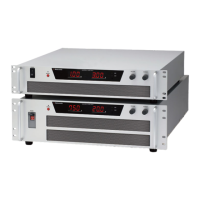
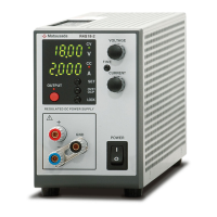
Describes the front and rear panels of the 1.1kW and 3kW type units.
Details the controls, indicators, and connectors on the front panel.
Details the connectors and terminals on the rear panel.
Details the controls and indicators on the front panel for larger models.
Details the connectors and terminals on the rear panel for larger models.
Provides physical dimensions for the 1.1kW and 3kW models.
Provides physical dimensions for the 6.4kW to 15kW models.
Introduces the TB1 connector for remote control and its pin assignments.
Lists critical safety precautions when using the TB1 remote control connector.
Provides detailed instructions and warnings for connecting the TB1 connector.
Emphasizes proper connection and grounding for optimal performance.
Illustrates how to connect the output cable for 1.1kW and 3kW models.
Illustrates how to connect the output cable for 6.4kW to 15kW models.
Explains the correct procedure for grounding the power supply unit for safety.
Shows proper and improper methods for connecting loads, including parallel connection.
Explains the basic operation modes: constant voltage and constant current.
Details how the unit operates in constant voltage mode based on load conditions.
Details how the unit operates in constant current mode based on load conditions.
Describes the automatic switching between voltage and current modes.
Lists common fault conditions indicated by the FLT light and their causes.
Guides through the initial settings for local programming mode.
Describes the default local mode setting and initial setup steps.
Provides step-by-step instructions for setting output voltage and current.
Explains how to configure the Over Voltage Protection setting.
Details methods for switching between local and remote operation modes.
Describes setting parameters externally in remote mode.
Continues the explanation of external parameter setting for voltage and current.
Explains the blackout protection feature and how to use/disable it.
Details the over-temperature protection circuit and recovery procedures.
Explains how to connect multiple units in series or parallel to increase output.
Details the procedure for connecting units in parallel for increased current output.
Describes how to set OVP using an external voltage signal.
Explains how to control the output ON/OFF state using a remote switch.
Introduces remote programming methods for controlling output.
Details controlling output voltage using an external voltage signal.
Details controlling output voltage using an external resistance.
Details controlling output current using an external voltage signal.
Details controlling output current using an external resistance.
Introduces outputs for monitoring voltage, current, and status signals.
Explains how to monitor output voltage and current values.
Describes the status outputs (CV, CC, FLT, OVP, OTP, AC fault) and their connection.
| Polarity | Positive or Negative |
|---|---|
| Input Voltage | 50/60 Hz |
| Operating Temperature | 0 to 40°C |
| Temperature Coefficient | 0.01%/°C |
| Display Resolution | 1 V |
| Interface | RS-232C |