Standard Tube Diameters
No Inserts 36 mm
No Dots 1.35”/1.375” or 35 mm
• 1.25” or 32 mm
•• 1.125” or 30 mm
••• 1.0” or 25 mm
Large Tube Diameters
No Dots 2” or 50.8 mm
• 1.77” or 45 mm
•• 1.5” or 38 mm
Use a 5 mm allen wrench to tighten the two (2) screws to mount the clamp to the axle re-
ceiving tube. e position and orientation outlined below are critical to the proper function
of SmartDrive and must be heeded.
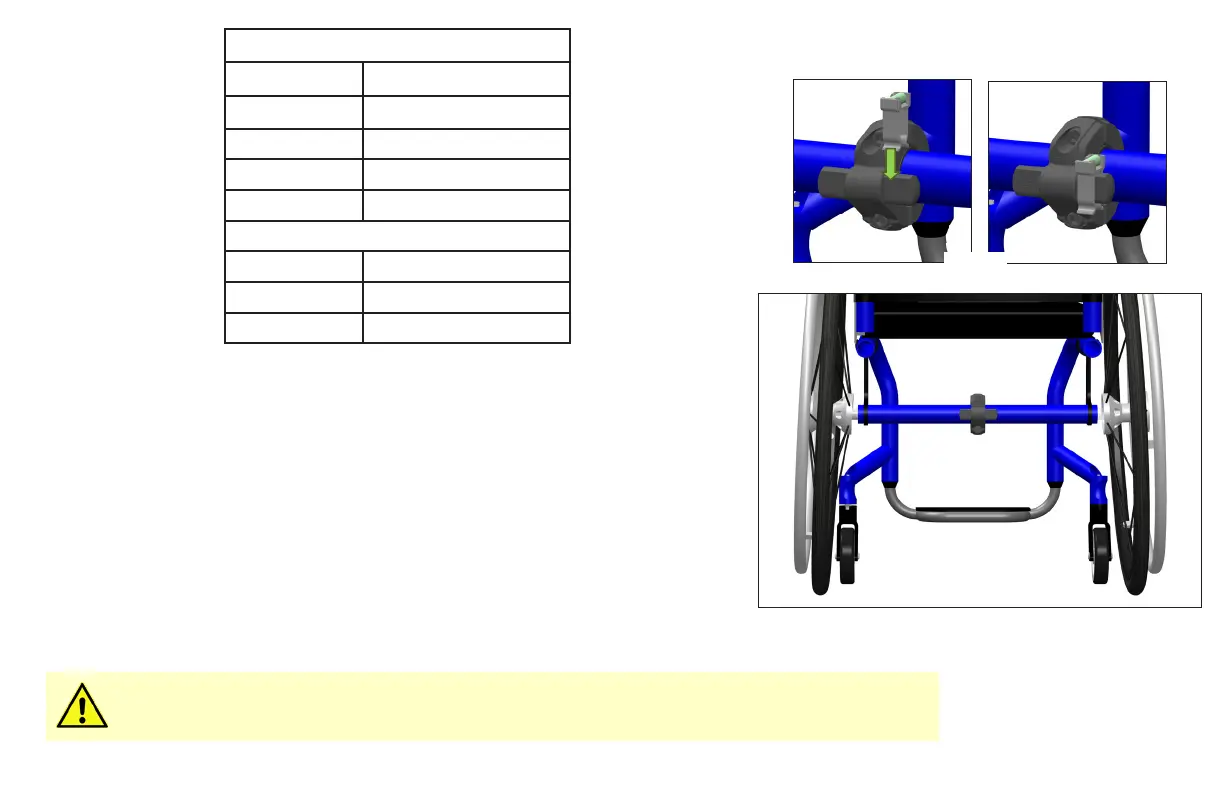
Make sure the “max” on the front of the clamp is right-side up. Use the provided bubble
level and attach to one of the posts to assist you in getting the clamp level (Fig. C). e
protrusions coming from the side of the clamp are to be positioned rearward with the extru-
sion ats perpendicular to the ground when the chair [with the user in it] is on a level plane.
e clamp must be positioned midway between the two rear wheels of the wheelchair on
the axle receiving tube (Fig. D). e two (2) screws should be tightened to 4 ft-lbs (5.4
N-m), xing it in this position and orientation. Failure to do this could cause the wheelchair
to not drive/ride straight and/or the clamp to move during use causing the SmartDrive to
not function properly.
Adjustments made to the wheelchair set-up could aect the orientation of the SmartDrive clamp.
Adjust the clamp whenever changes are made to the chair.
Fig. D
Fig. C