MAXEON SOLAR TECHNOLOGIES, LTD.
Safety and Installation Instructions - Document 001-15497 Rev.Z
©February 2023 Maxeon Solar Technologies, Ltd. All rights reserved. Specifications included in this manual are subject to change without notice.
No Maxeon module should be mounted at a site where it may be
subject to direct contact with salt water, or other aggressive
environment.
Modules should not be installed near flammable liquids, gases, or
locations with hazardous materials; or moving vehicules of any type.
Performance Series Mounting Orientation
Performance Series (P-Series) modules are designed to be installed in
landscape orientation. In landscape orientation, P-series modules
maintain higher power under row to row shading and edge soiling.
5.2 Mounting Configurations
Mounting system must provide a flat plane for the modules to be
mounted on and must not cause any twist or stress to be placed on
the Module, even in case of thermal expension.
Modules may be mounted at any angle from horizontal to vertical.
Select the appropriate orientation to maximize sunlight exposure.
Maxeon recommends for a good performance of the system
(reduction of soiling effect/water pooling) a minimum of 5˚ tilt angle.
The cleaning frequency must be increased for modules installed with
a very low angle.
Commercial modules (128 cells) frames have permanently attached
stacking pins located a 20mm zone on the long side frame at 388-408
mm. Mounting system hardware used with commercial modules must
account for the presence of these stacking pins (see Appendix).
Specific information on module dimensions and the location of
mounting and grounding holes is provided in Appendix.
In order to prevent water from entering the junction box, which could
present a safety hazard, modules should not be mounted such that
the front/top glass faces downward (e.g., on a tracking structure that
positions the module with the junction box facing skyward during
sleep mode).
We also want to remind that the watertightness is not ensured by the
modules but by the mounting system and that drainage should be well
designed for Modules.
Clearance between the module frames and structure or ground is
required to prevent wiring damage and allows air to circulate behind
the module. The recommended assembling clearance between
modules installed on any mounting system is a minimum of 50 mm
distance.
When installed on a roof, the module shall be mounted according to
the local and regional building and fire safety regulations. In case the
module is installed in a roof integrated PV-System (BIPV), it shall be
mounted over a watertight and fire-resistant underlayment rated for
such application
Modules mounting systems should only be installed on building that
have been formally considered for structural integrity, and confirmed
to be capable of handling the additional weighted load of the Modules
and mounting systems, by a certified building specialist or engineer.
Mounting system supplier shall manage the galvanic corrosion which
can occur between the aluminium frame of the Modules and
mounting system or grounding hardware if such devices is comprised
of dissimilar metals.
The module is only certified for use when its factory frame is fully
intact. Do not remove or alter the module frame. Creating additional
mounting holes or removing the stacking pins may damage the
module and reduce the strength of the frame, therefore are not
allowed. Using mounting Clamps or clips with additional grounding
bolts or grounding metal sheets could be in compliance with this
Safety and Installation Instructions manual subject to conditions of
Section 4.1
Modules may be mounted using the following methods only:
1) Frame Holes: Secure the module to the structure using the
factory mounting holes. Four M6 or M8 stainless steel bolts,
with nuts, washers, and lock washers are recommended per
module. Bolts to be fasten according to racking supplier
recommendations. Refer to Appendix for the module
dimensions and mounting hole locations.
2) Pressure Clamps or Clips: Mount the module with the opposite
clips on the longer and/or shorter side of the frame of the
module. The clips allowed location should be according to Table
1.1. Installers should ensure the clamps are of sufficient
strength to allow for the maximum design pressure of the
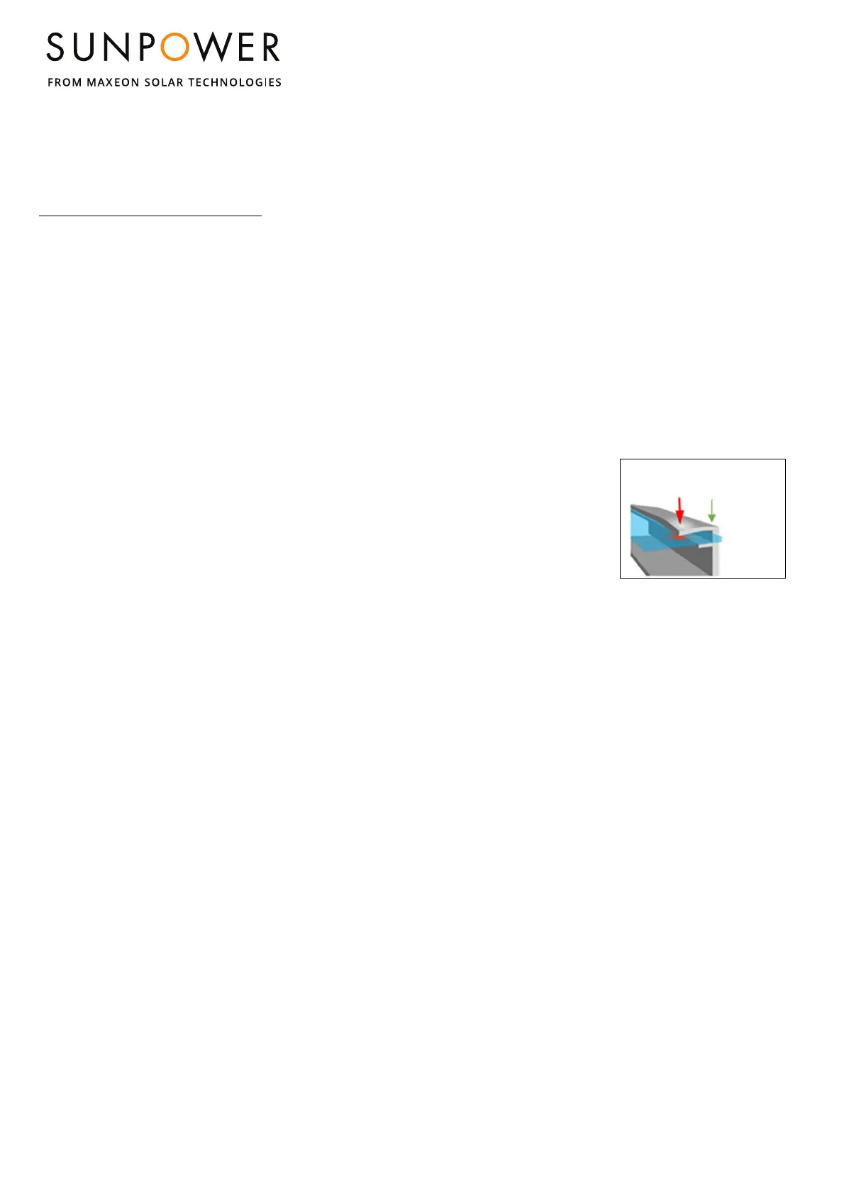
module. Clips and clamps are not provided by Maxeon. Clamps
must apply force collinear with the ‘wall’ of the module frame
and not only to the top flange. Clamps shall not apply excessive
force to the top frame, warp the top flange, or contact the glass-
these practices void the module warranty and risk glass
breakage. Figure 1a
illustrates locations for top
frame clamp force. Avoid
clamping within 50mm of
module corners to reduce
risk of frame corner
deflection and glass
breakage. When clamping
to the module frame,
torque should never exceed 15 N.m to reduce chances of frame
deformation, if the clamp datasheets show a specific torque
value which is lower than 15 Nm the installer should follow the
torque value which ever is more stringent. A calibrated torque
wrench must be used. Mounting systems should be evaluated
for compatibility before installing specially when the system is
not using Clamps or clips. Please contact Maxeon for the
approval of the use of non-standard pressure clamps or clips
where torque values are higher than otherwise stated.
Minimum clamp width allowance is ≥35mm, and for corner
clamping the minimum clamp width is: ≥50mm. Clamps should
not be in contact with the front glass and clamps should not
deform the frame.
Maxeon does not recommend nor endorse the application on
the modules of clamps which, as part of their grounding or
earthing function, have teeth or claw features (see Figure 2)
which may, individually or cumulatively, cause the module
breakage due to (and without limitation):
i) the grounding features touching the front glass which is
incorporated into the module due to the position of such
grounding feature,
ii) the shape, the position or the number of the grounding
features deforming the module top frame, or
iii) the clamp being over-torqued during the installation.
Force must not deform
top frame flange or
glass may break
Force has
to be
applied in
line with
frame
wall
Figure 1a: Clamp Force Locations
 Loading...