MAXEON SOLAR TECHNOLOGIES, LTD.
Safety and Installation Instructions - Document 001-15497 Rev.Z
©February 2023 Maxeon Solar Technologies, Ltd. All rights reserved. Specifications included in this manual are subject to change without notice.
Maxeon shall not be
liable for any damages or
losses whatsoever arising
from the use by the
Installer of any such
clamps on its modules,
and disclaims all
warranties, express or
implied, applicable to
those modules should
they be damaged in any way by such clamps. Therefore, the use
of the above mentioned clamps by the Installer is at the
Installer's sole risks.
3) End Mount: End mounting is the capture mounting of the
length of the module’s shorter frames with clamps on each
shorter sides of the frame. Three different configurations are
possible: 1) with two mounting rails under the complete length
of each shorter side of the Modules, (See Table 1.2), 2) with two
mounting rails parallel to the long side of the Modules (See
Table 1.2) and 3) without any mounting rail (See Table 1.2). The
end-mounting rails and clips or clamps (identified as A
(1&2&3&4)
in Table 1.1) must be of sufficient strength to allow for
maximum designed test pressure of the module. Verify this
capacity with the mounting system of vendor before
installation.
4) Hybrid Mount: Combination with clamps or clips located on
longer or shorter sides of Modules are also possible, see Table
1.2 for allowed configurations. In any case, four clampings
points are needed.
5) Maxeon specified or Maxeon supplied mounting systems.
Modules mounted with strict adherence to Maxeon
documentation, using hardware systems supplied by or
specified by Maxeon.
Figure 2 and Table 1.1 below demonstrate the mounting locations and
Tables 1.2 and 1.3 give allowed load ratings (designed test value) for
Maxeon modules.
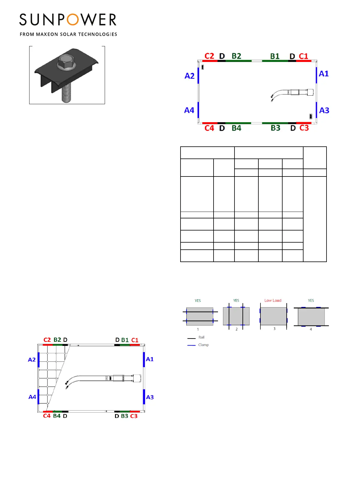
Figure 2: Mounting Zone locations for Maxeon modules
For P3-COM, MAX3 96, 104, 112 cells and MAX6 66 cells:
For 128 cells, P-Series and MAX5/MAX6 Commercial:
Table 1.1: Approved module clamping/direct fixation zones
Module Configuration
Mounting zone distance from
corner in (mm)
1
Frame
holes
E
Module size
Frame
type
A B C
(1&2&3&4)
(1&2&3&4)
(1&2&3&4)
(1&2&3&4)
96 cells, 104
cells (MAX3),
112 cells and
and P3 RES+
G3
(Black)
Silver &
G4.1 &
G4.2 &
G4.3
50-350
150-380
50-150
As per
Drawing in
the Table 2
112 AC ready G5.2 50-350 272-453 50-272
128 cells
G4 &
G4.1
50-350 408-880 50-375
P3-COM
G4.2 &
G4.3
50-350 408-833 50-375
MAX6 (66 cells) G5.2 50-350 265-514 50-265
MAX6 COM
(72 cells)
G4.2 &
G5.6
50-350 296-536 50-296
D - There is a 20mm zone at 388-408mm from the corner where mounting is not
allowed due to the module stacking pin feature. Applicable to 128 and 96 cell
commercial only.
1) No part of the module clamp may extend beyond this area.
Figure 3: Mounting Configurations
Configurations 1 and 2 show mounting with rail support, 3 and 4
show mounting without rail support. In “With Rail Support” the rails
becomes conventional or rails transverse while “Without Rail
Support” becomes end mounted in long or short side. In the case
when the glass deflects it would not deflect in the rails for additional
support.
Figure 2
 Loading...