MAXEON SOLAR TECHNOLOGIES, LTD.
Safety and Installation Instructions - Document 001-15497 Rev.Z
©February 2023 Maxeon Solar Technologies, Ltd. All rights reserved. Specifications included in this manual are subject to change without notice.
Table 1.2: Mounting Zone Design Load Ratings for Racking system
without rail support underneath the module. Refer to configuration
3 and 4 in Fig.3
Module
Configuration
Wind (up & down) / Snow (down)
(units in Pa) (***)
Module
size
Frame
type
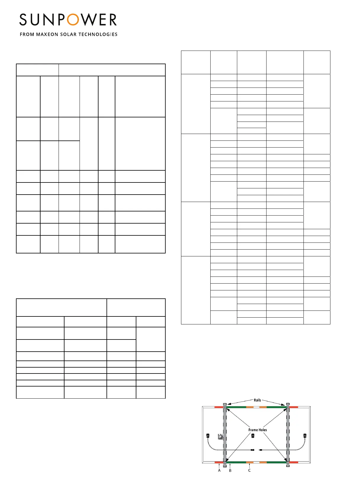
End
Mount
A
(1&2&3&4)
Frame
Holes
E
(1&2&3&4)
B
(1&2&3&4)
C
(1&2&3&4)
or B + C
(B
1&3
+C
2&4
or
B
2&4
+C
1&3
)
Or A + B
(A
1&3
+B
2&4
or
A
2&4
+B
1&3
)
Or A + C
(A
1&3
+C
2&4
or
A
2&4
+C
1&3
)
96 cells
G3
Black &
Silver
2400/
2400
(*)
2400/
5400
2400/
5400
2400/2400
104 cells
(MAX3)
and 112-
cells
(MAX3)
G4.2
1800/
1800
112 AC
Ready
G5.2
1800/
1800
3600/
3600
2400/
2400
1800/1800
P3 RES+ G4.3
1300/
1600
1600/
2400
1600/
2400
1300/
1600
128 cells
G4 &
G4.1
Not
applicable
(**)
2400/
5400
3600/
3600
2400/2400
P3-COM
G4.2 &
G4.3
1600/
1600
1600/
2400
1600/
2400
1600/1600
MAX6 (66
cells)
G5.2
1600/
1600
3600/
3600
3600/
3600
1600/1600
MAX6-
COM
(72 cells)
G5.6
1067/
1200
3600/
3600
3600/
3600
1600/1600
(*): 5400Pa is allowed with clamps and mounting rails along the longer side of the frame
(**): 2400/2400Pa are allowed with clamps and mounting rails along the longer side of
the frame
For Rooftop application 1200/1200Pa is allowed with only clamps
(***) Safety factor of 1.5 included
Table 1.3: Mounting Zone Load Ratings for Racking system with rail
support. Refer to Configuration 1 and 2 in Fig.3
Module Configuration
Wind (up & down) /
Snow (down)
(units in Pa) (***)
Module size Frame type B
(1&2&3&4)
C
(1&2&3&4)
96 cells and P3 BLK
G3 (Black &Silver) &
G4.1 & G4.2
2400 / 5400
2400 / 2400
104 cells (MAX3) and
112-cells (MAX3)
G4.2 3600/5400
112 AC Ready G5.2 2800/3600 1800/1800
P3 RES+ G4.3 1600/3600 1600/3600
128 cells G4 & G4.1 3600 / 5400 2400/ 3600
P3-COM G4.2 & G4.3 2000/2400 1600/2400
MAX6 (66 cells) G5.2 3600/6000 2800/2800
MAX6 COM
(72 cells)
G5.6 3000/5400 2400/2400
Table 1.4: Mounting Zone Load Ratings for Performance Modules
Applicable
Products
2
Mounting
Zone
Distance
from
corner
(mm)
Wind (up &
down) /
Snow(down)
(units in Pa)
3
Mounting
Method
P3 UPP
(2066 x 1160
x35mm
A 183-283
1600/2400
Clamp
B 466-566
1600/3600
4
C 783-833
1600/1600
D 260-320
1600/1600
E 465-565
1600/2400
Frame
Holes
2
383 (1300)
1600/1600
Bolt
504 (1058)
1600/3600
683 (700)
1600/1600
833 (400)
P5 UPP &
P6 COM-
M
(2384 x 1092 x
35mm)
A 50-546
800/1600
Clamp
6
B 546-692
1600/3600
4
C 692-1042
1333/3600
D 0-323
933/933 Clamp
7
E 546-692
1600/3600 Clamp
8
F 546-692
1600/2000 Clamp
9
G 0-323
933/933 Clamp
10
Frame
Holes
2
492 (1400)
1600/3600
Bolt
5
642 (1100)
1600/3600
992 (400)
1160/1160
P6 RES
BLK &
COM-XS
(1808 x 1086 x
30mm) &
(1808 x 1092 x
30mm)
A 50-402
1333/1333
Clamp
6
B 402-502
1600/3600
B2 217-617
1333/1800
C 502-754
1200/1333
D 221-321
1066/1066 Clamp
7
E 402-502
1200/1800 Clamp
8
F 50-100
1300/1300 Clamp
9
G 0-221
1066/1066 Clamp
10
P6 COM-S
(2185 x 1092 x
35mm)
A 50-496
1066/1200
Clamp
6
B 496-596
1600/3600
C 596-942
1066/1600
D 223-323
933/1600 Clamp
7
E 496-596
1200/1867 Clamp
8
F 50-100
1066/1200 Clamp
9
G
0-100
666/800
Clamp
10
100-323
1066/1066
Frame
Holes
2
1100(392)
1600/3600
Bolt
1400(542)
1600/3600
2 Refer to Table 2 for different mounting hole locations
3 Safety Factor 1.5 included
4 IEC validated
5 Minimum washer size of 24mm in diameter is required.
6 Long Side Mounting, Rails Perpendicular to Mounting Frame
7 Short Side Mounting, Rails Parallel to Mounting Frame
8 Long Side Mounting, Rails Parallel to Mounting Frame
9 Long Side Mounting, Point Supported (Bottom Flange Mounting)
10 Corner Mounting (Short Side), minimum of 50mm clamp is required.
Figure 4: Mounting Zone Locations for Performance modules
For P3, P5 UPP and P6 (COM-M, COM-S, RES BLK, COM-XS)
 Loading...