Do you have a question about the Maxeon Sunpower and is the answer not in the manual?
Essential precautions for safe installation, handling, and electrical connections.
Refer to local codes for grounding PV arrays and mounting frames.
Connect modules in series to achieve desired voltage output. Do not exceed max system voltage.
Combine modules in parallel to produce desired current output. Fuse strings.
Modules can be mounted at any angle. Minimum tilt angle of 5° recommended for performance.
Secure modules using factory mounting holes with M6 or M8 stainless steel bolts.
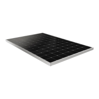
This document outlines the safety and installation instructions for Maxeon PV Modules, manufactured by Maxeon Solar Technologies, Ltd. These modules are designed for photovoltaic power generation in various environments, including Europe, Asia, Australia, Latin America, and Africa. The manual covers several Maxeon series, including X-series, P-Series, MAX3, MAX5, and MAX6 PV Modules. It is crucial to read and understand these instructions thoroughly before installing, wiring, or using the product, as failure to comply will invalidate the Maxeon Limited Warranty.
Maxeon PV Modules are designed to convert sunlight into direct current (DC) electricity. They are intended for installation on buildings or as freestanding units, meeting or exceeding the requirements of IEC 61215 Edition 3-2016 and IEC 61730 Edition 1 and 2 series for Class II applications. The modules are not designed for use with artificially concentrated sunlight. They can be connected in series to achieve desired voltage output or in parallel to produce desired current output, provided specific conditions are met, such as using only the same type of modules in a combined source circuit. Bypass diodes are factory installed within the modules to manage current flow. The modules are compatible with transformer-less inverters when used as an ungrounded PV source. Functional system grounding of a polarity (positive or negative) is optional and may be subject to local requirements. The modules are designed to withstand specific positive and negative pressure loads, making them suitable for various environmental conditions, including snow-prone and high-wind environments, when mounted correctly.
The modules are designed for versatile mounting, allowing installation at any angle from horizontal to vertical. Maxeon recommends a minimum tilt angle of 5° for optimal system performance, reducing soiling and water pooling. For commercial modules (128 cells), frames have permanently attached stacking pins that must be accounted for during mounting. The modules should be installed in locations that ensure adequate ventilation, especially in hot environments, and minimize permanent shading of cells. Permanent shading, defined as shade cast over the same position of the solar module throughout generation hours, should be avoided as much as possible, particularly at mid-day, to prevent significant energy production reduction.
Mounting can be achieved through several methods:
For bifacial modules, specific considerations apply to maximize bifacial gain:
Maxeon recommends regular visual inspection of all modules to ensure safe electrical connections, sound mechanical connections, and absence of corrosion. This inspection should be performed annually by trained personnel, or more frequently depending on environmental conditions. Periodic cleaning of modules is recommended but not required, though it can improve performance, especially in regions with low annual precipitation.
For cleaning, use potable, non-heated water. Normal water pressure is sufficient, but pressurized water up to 100 bar (min. 50 cm distance) can be used. Cleaning should not be performed at high outside temperatures. Fingerprints, stains, or dirt accumulations on the front surface can be removed by first rinsing the area, letting it soak for 5 minutes, then re-wetting and using a soft sponge or seamless cloth to wipe the glass surface in a circular motion. Fingerprints can typically be removed with a soft cloth or sponge and water after wetting. Harsh cleaning materials, scouring powder, steel wool, scrapers, blades, or other sharp instruments should not be used, as they can invalidate the product warranty. Dry cleaning and spinning brushes are not recommended for anti-reflective (AR) coated module surfaces.
During installation, modules should be handled with care. They should not be placed face down on abrasive surfaces like roofs, driveways, wooden pallets, railings, or stucco walls. The front surface glass is sensitive to oils and abrasive surfaces, which can lead to scratches and irregular soiling. Modules with anti-reflective coated glass are prone to visible finger print marks, so handling with gloves (not leather) or limiting direct contact with the front surface is recommended. Any resulting fingerprints will naturally disappear over time or can be reduced by following washing guidelines. Module coverage with colored plastic tarps or similar during installation is not recommended as it can cause permanent front glass discoloration. Vacuum lifting pads can also cause permanent marks on the front glass. Modules should never be lifted or moved using the cables or the junction box. Unconnected connectors must be protected from pollution (e.g., dust, humidity, foreign particles) prior to installation. Chemical contact with connectors (greases, oils, organic solvents) should be avoided to prevent stress cracking. Modules should not be installed or handled when wet or during high winds. Drain holes should not be blocked, and water should not be allowed to pool in or near module frames.
| Efficiency | Up to 22.8% |
|---|---|
| Temperature Coefficient | -0.29%/°C |
| Manufacturer | Maxeon Solar Technologies |
| Warranty | 25 years |
| Technology | IBC (Interdigitated Back Contact) |