11
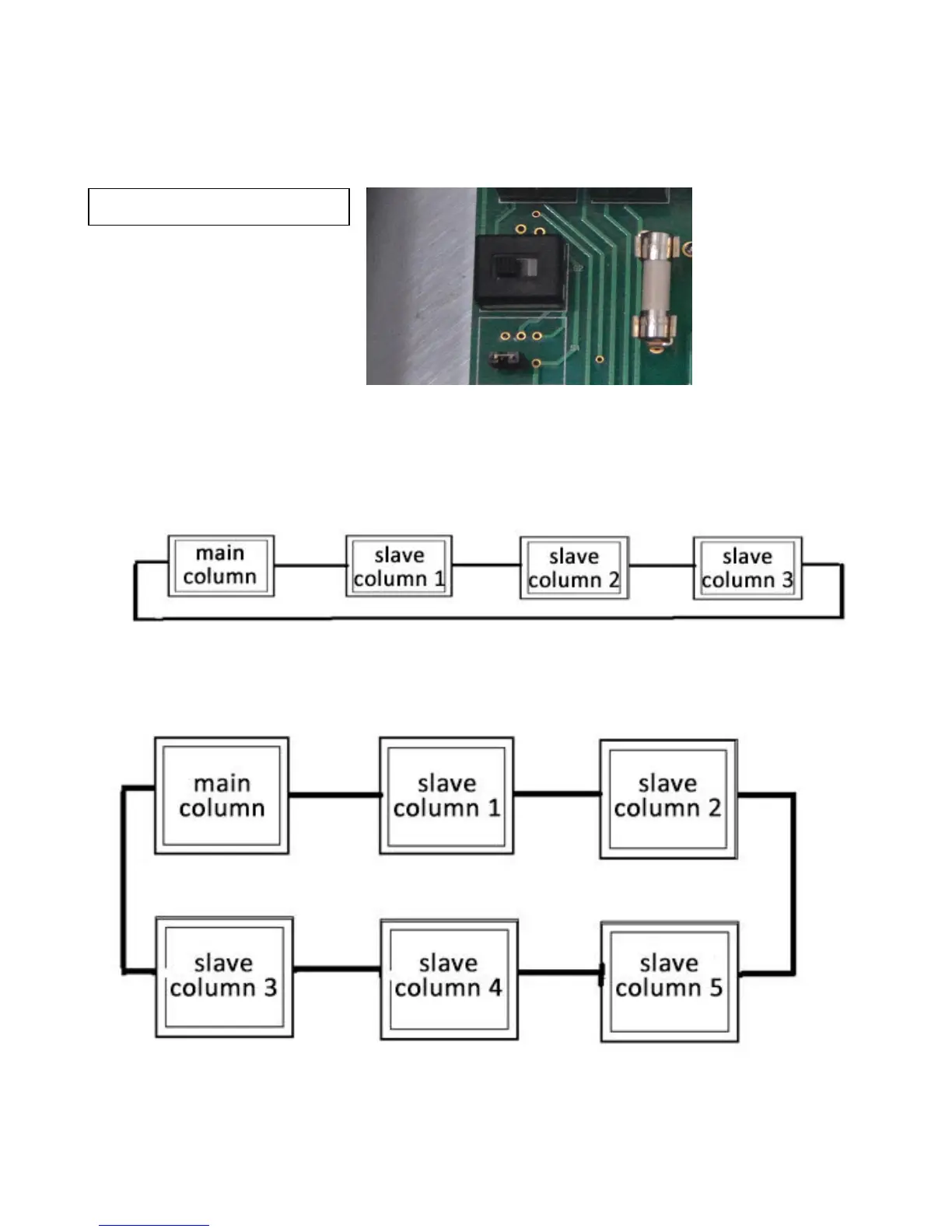
In case of an emergency, use the key to access the control panel and move the switch to right
side as illustrated below so that the equipment can be operated without the communication
cables connected. The switch is located at the extreme lower left side of the circuit board next to
the fuse holder.
Make sure that you have connected all communication cables according to Fig. 1 and Fig. 2
before operation.
Four Column Configuration
Fig. 1
Six Column Configuration
Fig. 2