20
model no. 054-2433-0 | contact us 1-888-670-6682
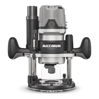
LED WORKLIGHTS (fig 17)
Your router motor has 3 built-in
worklights located around the collet to
provide high visibility of the workpiece
when cutting. These lights are always on
when the switch is in the on position
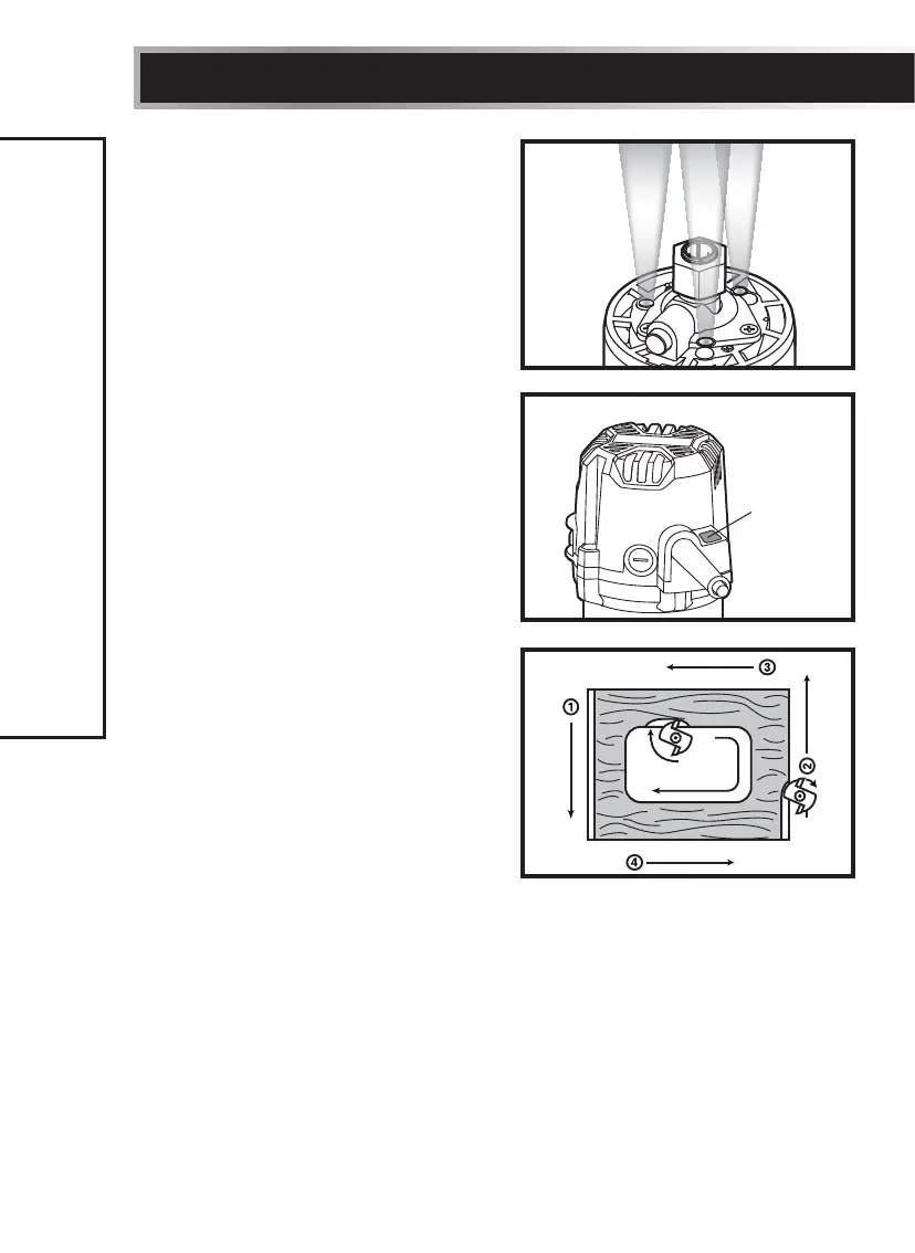
LIVE-TOOL INDICATOR LIGHT
(fig 18)
Your router also has a live-tool indicator
light, located on the motor housing top
cap where the power cord enters the
motor housing. This green light is always
on when the router motor is plugged into
a power source.
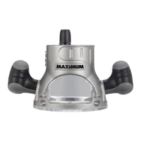
FEEDING THE ROUTER (fig 19)
The secrets to professional routing are
a careful set-up for the cut, selecting
the proper depth of cut, knowing how
the cutter bit reacts in your workpiece,
and the rate and direction of feed of the
router.
DIRECTION OF FEED-EXTERNAL
CUTS (fig 19)
The cutter bit rotates clockwise (when installed on a router table, the rotation
is counter-clockwise). Feeding the bit from left to right will cause the bit to pull
the router towards the workpiece. If the router is fed in the opposite direction
(right to left), the rotating force of the cutter bit will tend to throw the bit away
from the workpiece. This is called “Climb-Cutting”.
OPERATING INSTRUCTIONS
fig 17
fig 18
Live-tool
indicator
light
fig 19
Router feed
direction
Router feed direction