Page2
MERLIN
INSTALLATION
(continued)
6
Followtheinstructionssuppliedwiththeantenna
mountandsecurethemasttothemount.
9
7
8
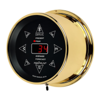
Feedthecablesthroughthewalltowheretheread-outisgoingto
belocated.Attachthewirestotherearoftheread-outasshown.
Theredwirefromthedirectionsensorcableconnectstoterminal#4.
thegreenwiretoterminal#5. Connecttheblackandwhitewires
fromthespeedsensortoterminals#1and#2. Thepolaritydoes
notmatter. leshielditselfisnotconnected,shieldedAlthoughthecab
cablem ConnectthewiresfromtheACadaptertotheustbeused.
meter itydoesnotmatter. Thepolar . (DoNOTadjustthenutsthat
arealreadyonthemeter).
Mountthebr verthecablefeed-thrassread-outdirectlyo u-hole
toavoidcrimpingthewireunderthelip. Werecommendmounting
theread-outononeofourpre-drilledandcenteredpanels.Plugthe
powersupplyintoa110VACpoweroutlet.
8 FEET
CHIMNEY
MOUNT
VENT-PIPE
MOUNT
TRIPOD
MOUNT
WALL
MOUNT
EVE
MOUNT
CABLE-HOLE
WALL
Securethewiretothebuildingusingcableclips(donotuseregular
staples).Formadriploopwherethewiresentertheholedrilled
throughtheexteriorwall.Caulktheholewhendone.
DRIP
LOOP
FROM AC
ADAPTER
BRASS
NUTS
CAULK
WIRE
CABLE
CLIPS
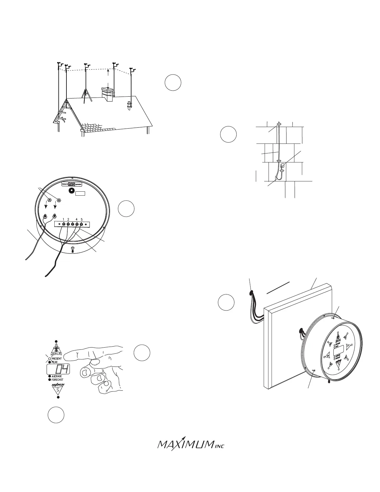
WhenMerlinfirststartsupitwill
performabriefself-testandthen
gotothe"Present"functionmode.
Resetallmemoryfunctions(seeoperatinginstructions).
ResettinggivesMerlinafreshstartingpointforyour
reference.
10
11
SCREW
SCREW
PANEL
GREEN
WIRE
RED
WIRE
SelectUnitsof
Measurment
AC ADAPTOR
(NOPOLARITY)
3
www.ShopAEMC.ca
Shop for AEMC products online at:
1.800.561.8187