DIP Switch Position Table
Control
Signal
SW1
Signal
SW2
Offset
SW3
Characteristic
0-10V OFF OFF OFF
2-10V OFF ON OFF
0-20 mA ON OFF OFF
4-20 mA ON ON OFF
2
© 2019 Maxitrol Company, All Rights Reserved.
EXA Modulating Valve Series
The PWM output will give a feedback to correspond with the
current valve position between the programmed minimum and
maximum positions. The duty cycle range is always scaled
from the programmed minimum to the programmed maximum
position.
Frequency: 200 Hz ± 1 Hz
Resolution: 9-bit (0.29% duty cycle)
Duty Cycle: 3% @ programmed minimum position
97% @ programmed maximum position
Output Impedance: 3.2 kΩ ± 0.1 kΩ
Output High Voltage: 5.0 V nominal
5.25 V maximum
NOTE: Output high level varies with the load current at the
PWM output.
Output Low Voltage: 0.0 V + 0.01 V
Pin 1: (+) positive polarity
Pin 2: (-) negative polarity
(see Figure 2)
Connection: TYCO MTA-100 or EQ.
NOTE: Optional pre-wired connector for control signal/power/
feedback available. Contact Maxitrol Customer Service
for details and availablity.
Table 3: Dip Switch Position Table
Flow Capacity in Btu/h @ 1” Pressure Drop:
Model Nat Gas LP
EXA40 (3/8”) 190K 315K
EXA40 (1/2”) 215K 355K
EXA50 (1/2”) 385K 640K
EXA50 (3/4”) 435K 725K
EXA60 (3/4”) 670K 1115K
EXA60 (1”) 780K 1300K
Table 1: Sizing Chart
SPECIFICATIONS CONTINUED
Sizing
Valve sizing and selection is based on the typical 1.0” w.c.
pressure drop allowance at maximum ow rate. Using the sizing
chart (table 1), nd the closest ow rate which meets or exceeds
the appliance’s maximum modulated ow rate.
POSITION FEEDBACK OUTPUT SPECIFICATION
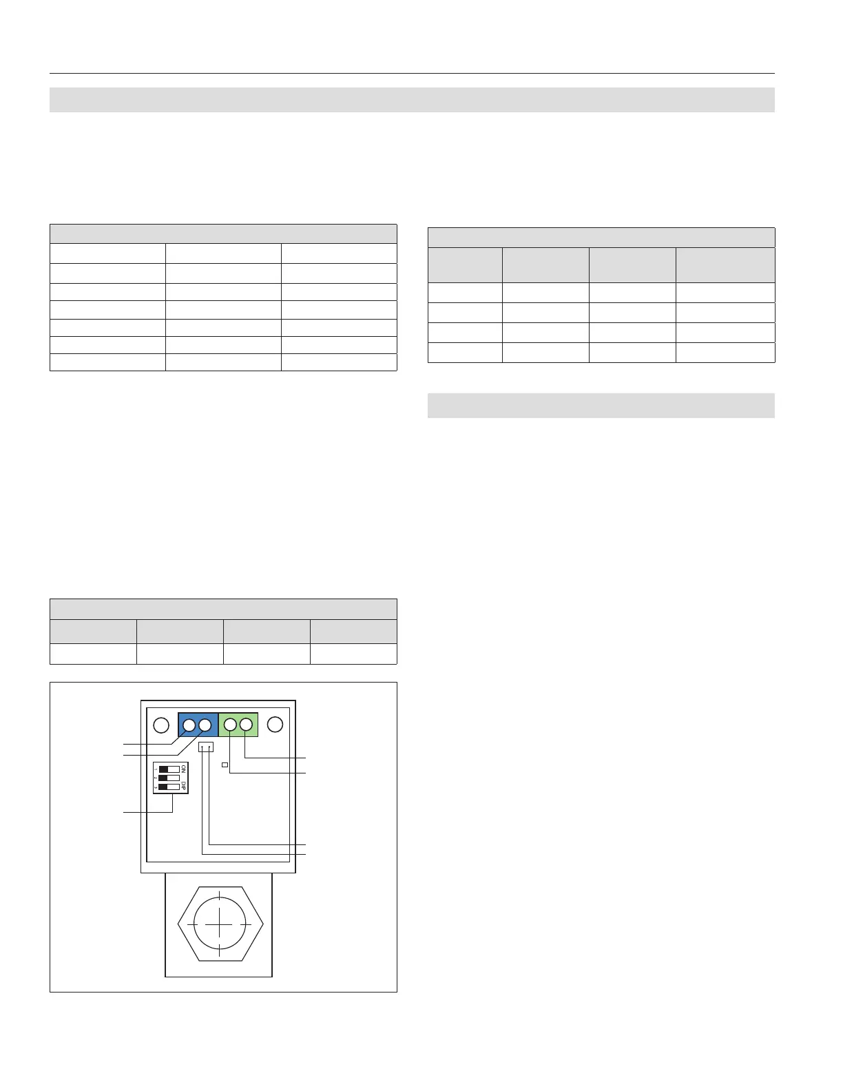
Figure 2: EXA Modulating Valve Series Connections
Power:
Terminal 4
Terminal 3
Position Feedback:
Pin 1
Pin 2
Control Signal:
Terminal 1
Terminal 2
DIP Switches
(Table 3)
Table 2: Connection Table
© 2019 Maxitrol
Control Signal
The control signal indicates a position within the valve’s
programmed range of modulation.
NOTE: Control signal is polarity sensitive. Connect control
signal positive (+) to terminal 1 and control signal
return (-) to terminal 2 (see table 2).
The control signal is “scaled” between the high and low re
setting of the valve. The minimum control signal will correspond
to the programmed low re setting, and the maximum control
signal will correspond to the programmed high re setting.
Connection Table
Terminal 1 Terminal 2 Terminal 3 Terminal 4
Signal (+) Signal (-) Power (+) Power (-)
DIP Switches
A three (3) position DIP switch is located on the PCB (see Figure
2). Change the signal type and offset by changing the position
of DIP switches. (For DIP switch position and corresponding
current/voltage ranges, see Table 3).
 Loading...