4
Maxitrol Company
23555 Telegraph Rd., P.O. Box 2230
Southeld, MI 48037-2230 U.S.A.
www.maxitrol.com
© 2019 Maxitrol Company,
All Rights Reserved.
EXA_X1_MS_EN_06.2019
EXA Modulating Valve Series
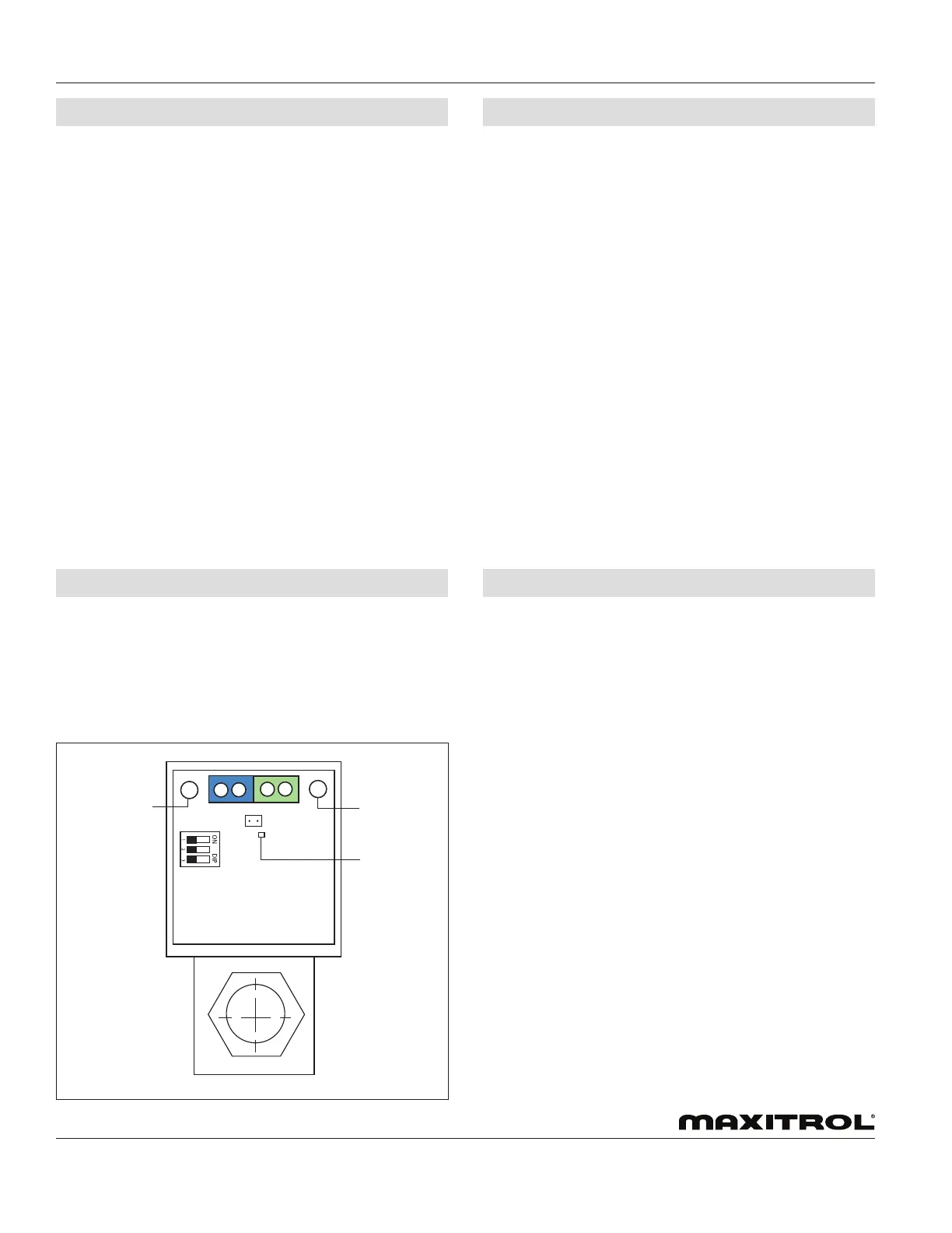
Figure 4: EXA Modulating Valve Series Adjustment Controls
Button 1
Button 2
LED
© 2019 Maxitrol
To enter into the low re setting mode, press and hold Button
#2 until the LED light blinks red. Release. The valve is now in
the low re setting mode. buttons #1 and #2 are used to set the
desired low re setting.
To decrease gas ow slowly, press button #2. Each button press
will decrease gas ow by the minimum available step size. To
decrease gas ow rapidly, hold button #2. Holding the button
down allows the valve to auto step and eliminates the need to
repeatedly press the button.
To increase gas ow slowly, press button #1. Each button press
will increase gas ow by the minimum available step size. To
increase gas ow rapidly, hold button #1. Holding the button
down allows the valve to auto step and eliminates the need to
repeatedly press the button.
To save the low re setting, simultaneously hold Buttons #1 and
#2 until the blinking LED turns OFF.
NOTE: Controls left in any setting mode will default to the
current settings and return to normal operating mode
after 5 minutes of inactivity.
LOW FIRE SETTING - BUTTON #2
The EXA STAR modulating valve series has two (2) buttons and
a communication LED for the user interface. The buttons are
used to set the valve for high and low re settings (see gure 4).
1. High Fire Setting (LED will be solid red)
2. Low Fire Setting (LED will be blinking red)
3. Operating Mode (LED will be OFF)
CONNECTIONS
VALVE SETTING
Step 1: Remove 2 screws holding cover.
Step 2: Switch power and control signal off.
Step 3: Connect switched OFF 24V (AC/DC) power source to
terminals 3 and 4. Note polarity when using a DC power
source or if one leg of an AC transformer secondary is
externally grounded or is sharing power with another
half-wave device (see gure 2, page 2).
Step 4: Set DIP switches to match available control signal
(see table 3, page 2).
Step 5: Connect control signal to terminals 1 and 2.
Observe polarity. Note that the return, or signal
ground, must be connected to terminal 2 (see gure
2, page 2).
Step 6: Switch power and control signal ON.
Step 7: Set valve (see “Valve Setting” in section below).
Step 8: Replace cover.
To enter the high re setting mode, press and hold Button #1
until the LED lights solid red. Release. The valve is now in the
high re setting mode. Buttons #1 and #2 are used to set desired
high re setting.
To increase gas ow slowly, press button #1. Each button
press will increase gas ow by the minimum available
step size. To increase gas ow rapidly, hold button #1.
Holding the button down allows the valve to auto step
and eliminates the need to repeatedly press the button.
To decrease gas ow slowly, press button #2. Each button press
will decrease gas ow by the minimum available step size. To
decrease gas ow rapidly, hold button #2. Holding the button
down allows the valve to auto step and eliminates the need to
repeatedly press the button.
To save the high re setting, simultaneously hold buttons #1 and
#2 until the LED turns OFF.
NOTE: Controls left in any setting mode will default to the
current settings and return to normal operating mode
after 5 minutes of inactivity.
HIGH FIRE SETTING - BUTTON #1
 Loading...