1
© 2013 Maxitrol Company, All Rights Reserved
DESCRIPTION
Selectra Series 14R electronic gas flame modulation systems
are designed primarily for make-up air heating, as components
of direct fired equipment. They may be field installed on existing
equipment or specified for new equipment installation.
The system uses Modulator or Modulator-Regulator valves,
ampliers which include low-re start, and integral or remote
temperature selection and a discharge air temperature sensor that
is mounted within a mixing tube.
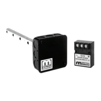
SYSTEM COMPONENTS
A1014R Amplier
A1014R (all remote temperature ranges)
Included Integral Ranges:
40º to 80ºF
55º to 90ºF
90º to 140ºF
110º to 160ºF
160º to 210ºF
Remote Temperature Selectors
TD114...................55° to 90°F w/override
0° to 40°F over set point
TD114A................................ 80° to 130°F
TD114A-1...........80° to 130°F w/override
0° to 40°F over set point
TD114B................................120 to 170°F
TD114C..............................160° to 210°F
TD114D..............................200° to 250°F
TD114E..............................100° to 250°F
TD114F..............40° to 80°F w/override
0° to 40°F over set point
TD114G...............................90° to 140°F
TD114-1........55° to 90°F w/120° to 170°F
override, use w/TS114
TD114-2...........55° to 90°F w/two outputs
TD114G-2........90° to 140°F w/two outputs
Remote Temperature Selectors Continued
IMPORTANT: The A1014R integral or remote temperature
selector’s (TD114) temperature range must match the temperature
sensor’s (TS114) temperature range. See page 7 for available
integral dial ranges.
Optional: ETD-1 enclosure, EFP-1 cover plate only - no enclosure
Discharge Air Temperature Sensors: use with Mixing Tube
TS114..........................................................................55° to 90°F
TS114A.....................................................................80° to 130° F
TS114B....................................................................120° to 170° F
TS114C....................................................................160° to 210° F
TS114D..................................................................200° to 250° F
TS114E..................................................................100° to 250° F
TS114F.....................................................................40° to 80° F
TS114G....................................................................90° to 140° F
TS114J.................................110° to 160° F, use w/ AD1014-1116,
TS214__...........................dual sensor - any combination
of 2 standard ranges available
Example 1 - TS214G....................55° to 90° F and 90° to 140° F,
use w/TD114 & TD114G, or TD214G (selector w/switch).
Example 2 - TS214AD..................80° to 130° F and 200° to 250° F,
use w/TD114A & TD114D, or TD214AD (selector w/ switch).
Mixing Tubes: (and sensor)
Lengths:
MT1-9 or 2-9............................9”
MT1-12 or 2-12......................12”
MT1-23 or 2-23......................23”
MT1-28 or 2-28......................28”
MT1-57...................................57”
Valves
Pipe Sizes:
M411........................... 3/8” & 1/2”
M511...........................1/2” & 3/4”
M611 ............................3/4” & 1”
MR212D...................1”, 1¼”, 1½”
MR212E.........................1½” & 2”
MR212G....................... 2½” & 3”
MR212J.......................4” anged
2 Speed Blower or Dual Fuel
Operation:
MR212D-2................1”, 1¼”, 1½”
MR212E-2.....................1½” & 2”
MR212G-2.....................2½” & 3”
MR212J-2....................4” anged
NOTE: M (Modulator) valve requires an
upstream pressure regulator for
low re & high re settings. MR
(Modulator/Regulator) valve
requires no upstream pressure
regulator up to 5 psi inlet.
TABLE OF CONTENTS
System Components....................................................................1
Dimensions..................................................................................2
Specications................................................................................3
Installation of Components............................................................3
Wiring Diagrams............................................................................4
Settings..........................................................................4-5
Valve Adjustments.........................................................................5
Field Service Checklist.................................................................6
Preliminary Circuit Analysis.........................................................7
Label Instructions..........................................................................7
Read these instructions carefully and completely before
installing or operating. Failure to follow them could result in a re
or explosion causing property damage, personal injury, or loss of
life. The product must be installed and operated according to all
local regulations.
Service and installation must be performed by a trained/
experienced service technician.
Series 14R Installation Instructions and Field Service Checklist