Manual CT165 & CT225 April 2008
www.max-power.com 6
It is essential to install a manual battery isolator and if possible an electric
battery isolator at the base of the thruster motor power line.
When using a manual battery isolator it must be visible, clearly marked & easily
accessible.
Thruster motor power supply (24V):
These values are given as an indication, assuming that the batteries are charged at
100% and in charge, that is 25.4V.
The performance data is measured with an approx. consumption of 560A and 22V for the
CT165, and 690A and 22V for the CT225, at the motor’s connections.
Please refer to the characteristics given by the manufacturer of the batteries that will be
used (see section 9 “Batteries”).
Power wiring:
Measure the shortest and most direct route possible between the battery(ies) and the
electric motor; remembering to allow for both “positive and negative” cables.
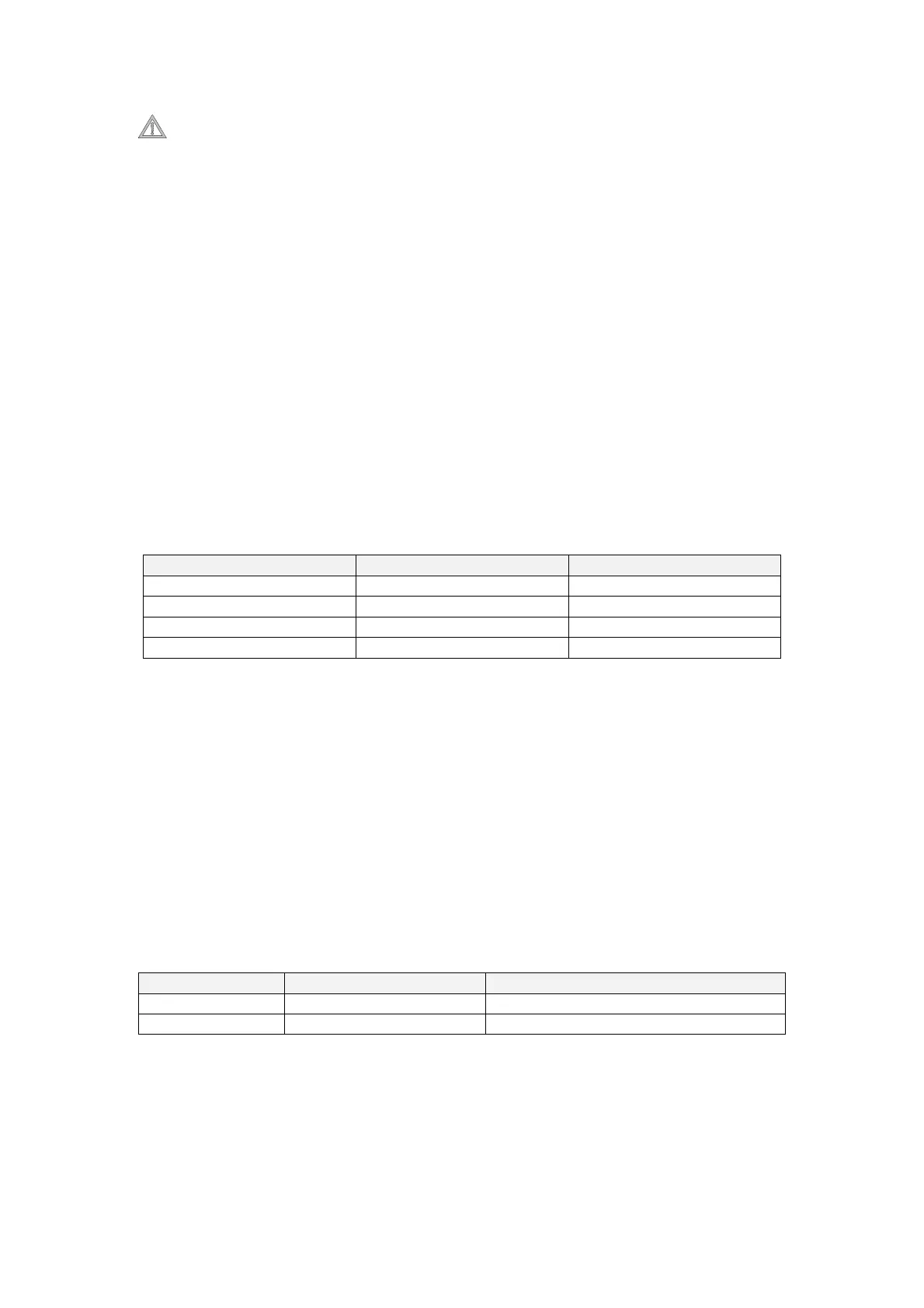
Recommended cable sections:
Cable lengths CT165 CT225
L ≤ 5 m (2,5 x 2) 70mm² 70mm²
5< L ≤ 10 m (5 x 2) 70mm² 95mm²
10 < L ≤ 15 m (7,5 x 2) 120mm² 150mm²
15< L ≤ 20 m (10 x 2) 150mm² 200mm²
For all connections, use appropriate terminals for the cable sections chosen.
It is possible to reduce the cable section to facilitate easy connection but only over a
short distance. In this case, appropriated crimp fittings should be used at the
connections.
Please consult the "Electrical installation" diagram p. 11 for more information
8. MAIN POWER FUSE
Fuse sizes for overcurrent protection are to be determined on the basis of the cable
sections in the circuit and NOT the amperage drawn by the appliance (thruster motor) in
the circuit.
Thruster Maximum Amperage Max Power Fuse size
CT165 / 12V 560A 250A
CT225 / 24V 690A 200A
9. BATTERIES
Thrusters are high amperage consumers with instantaneous demands, thus, we
recommend you use maintenance-free “starting” type batteries, with high CCA outputs.
For example: Exide Maxxima 900, 12V, capacity 55Ah / starting current 800CCA.