3
PC4020 Design Notes
SYSTEM OVERVIEW
SECTION 1
1.0 Introduction
The PC4020 is a highly flexible and versatile control which will enable the installer to meet the
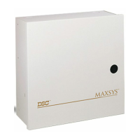
most demanding security requirements. The heart of the system is the main control panel, desig-
nated the PC4020, which is connected to other system elements using common 4 conductor
unshielded station wire. A few of the features available are:
• up to 128 zones (with the addition of zone expansion modules)
• 128 - 4 digit or 6 digit user codes with individually programmable system access
• 8 individual, fully programmable partitions
• 3 keypad Panic zones on each keypad
• 3 programmable voltage outputs on the main board (PGM, SW AUX and Main Bell Output)
• expandable up to 64 fully programmable relay outputs
• expandable up to 144 fully programmable low current outputs
• full upload/download control using an IBM PC and Hayes (TM) or Practical Peripheral 1200
baud modem
• 512 event buffer, time and date stamped which can be printed on premises or retrieved with
the DLS software
1.1 Terminology
1.1.1 Modules
Every keypad, zone expander, power supply/relay board, low voltage output board or printer
output board is a module. Before any module will operate properly it must be enrolled to the
system. Once a module is enrolled the panel will communicate with it via the COMBUS and the
module will function properly.
1.1.2 Enrolling
Enrolling is the term used for adding a module to the system. When the PC4020 is first powered
up it is not aware of any module connected. The first keypad you press a key on will automatically
be enrolled to the system as keypad 1 assigned to Partition 1. Once the first keypad is enrolled
you can enter Installer’s Programming and enroll any additional modules that are to be connected
to the system.
1.1.3 COMBUS
The COMBUS (Communications Bus) is the 4-wire cable to which all the modules are connected
in parallel. The main panel uses the COMBUS to communicate with all modules on the system. To
allow the panel to distinguish between the various modules each has a unique 16 bit address
programmed at the factory eliminating the need for setting DIP switches.
1.1.4 Partitions
A partition is a defined areas which will operate independently from other areas of the system. Up
to 8 partitions can be defined each with a variable number of zones and user codes assigned to
it. In addition, features may be enabled or disabled for each partition individually.
For example: Partition 1 of a system could have 20 user codes, have zones 5, 6 and 12 assigned
to it and be programmed to auto arm at 6:00 pm.