WWW.MAXTEC.COM • (800) 748-5355 11 ENGLISH
ELECTROMAGNETIC EMISSIONS
This equipment is intended for use in the electromagnetic environment specified below.
The user of this equipment should assure that it is used in such an environment.
EMISSIONS
COMPLIANCE
ACCORDING TO
ELECTROMAGNETIC ENVIRONMENT
RF Emissions (CISPR 11) Group 1 The MaxVenturi uses RF energy only for its
internal function. Therefore, its RF emissions
are very low and are not likely to cause any
interference in nearby electronic equipment.
CISPR Emissions
Classification
Class A The MaxVenturi is suitable for use in all
establishments other than domestic and
those directly connected to the public low-
voltage power supply network that supplies
buildings used for domestic purposes.
NOTE: The EMISSIONS characteristics of
this equipment make it suitable for use in
industrial areas and hospitals (CISPR 11 class
A). If it is used in a residential environment
(for which CISPR 11 class B is normally
required) this equipment might not oer
adequate protection to radio-frequency
communication services. The user might
need to take mitigation measures, such as
relocating or re-orienting the equipment.
Harmonic Emissions
(IEC 61000-3-2)
Class A
Voltage Fluctuations Complies
ELECTROMAGNETIC IMMUNITY
This equipment is intended for use in the electromagnetic environment specified below.
The user of this equipment should assure that it is used in such an environment.
IMMUNITY AGAINST IEC 60601-1-2: (4TH
EDITION) TEST LEVEL
ELECTROMAGNETIC
ENVIRONMENT
Professional
Healthcare Facility
Environment
Home
Healthcare
Environment
Electrostatic
discharge, ESD
(IEC 61000-4-2)
Contact discharge: ±8 kV
Air discharge: ±2 kV, ±4
kV, ±8 kV, ±15 kV
Floors should be wood, concrete,
or ceramic tile. If floors are covered
with synthetic material, the
relative humidity should be kept
at levels to reduce electrostatic
charge to suitable levels.
Mains power quality should be
that of a typical commercial
or hospital environment.
Equipment which emits high
levels of power line magnetic
fields (in excess of 30A/m) should
be kept at a distance to reduce
the likelihood of interference.
If user requires continued
operation during power mains
interruptions, ensure that batteries
are installed and charged.
Ensure that battery life exceeds
longest anticipated power
outages or provide an additional
uninterruptible power source.
Electrical fast
transients / bursts
(IEC 61000-4-4)
Power supply lines: ±2 kV
Longer input / output lines: ±1 kV
Surges on AC
mains lines (IEC
61000-4-5)
Common mode: ±2 kV
Diferential mode: ±1 kV
3 A/m power
frequency
magnetic field
50/60 Hz (IEC
61000-4-8)
30 A/m
50 Hz or 60 Hz
Voltage dips and
short interruptions
on AC mains
input lines (IEC
61000-4-11)
Dip>95%, 0.5 periods
Dip 60%, 5 periods
Dip 30%, 25 periods
Dip >95%, 5 seconds
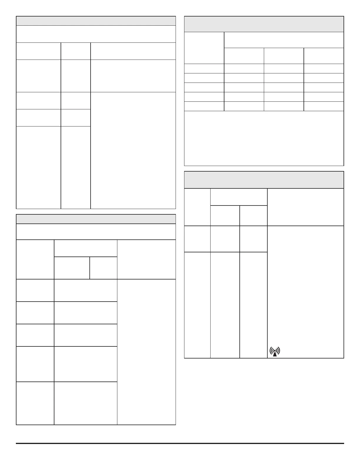
Recommended separation distances between portable and mobile
RF communications equipment and the equipment
RATED MAXIMUM
OUTPUT POWER OF
TRANSMITTER
W
Separation distance according to frequency
of transmitters in meters
150 kHz to 80 MHz
d=1.2/V1] √P
80 MHz to 800 MHz
d=1.2/V1] √P
800MHz to 2.5 GHz
d=2.3 √P
0.01 0.12 0.12 0.23
0.1 0.38 0.38 0.73
1 1.2 1.2 2.3
10 3.8 3.8 7.3
100 12 12 23
For transmitters rated at a maximum output power not listed above, the recommended
separation distance d in meters (m) can be estimated using the equation applicable to
the frequency of the transmitter, where P is the maximum output power rating of the
transmitter in watts (W) according to the transmitter manufacturer.
NOTE 1: At 80 MHz and 800 MHz, the separation distance
for the higher frequency range applies.
NOTE 2: These guidelines may not apply in all situations. Electromagnetic propogation
is aected by absorption and reflection from structures, objects, and people.
This equipment is intended for use in the electromagnetic environment specified below. The
customer or the user of this equipment should assure that it is used in such an environment.
IMMUNITY
TEST
IEC 60601-1-2: 2014 (4TH
EDITION) TEST LEVEL
ELECTROMAGNETIC
ENVIRONMENT - GUIDANCE
Professional
Healthcare Facility
Environment
Home
Healthcare
Environment
Conducted
RF coupled
into lines (IEC
61000-4-6)
3V (0.15 - 80 MHz)
6V (ISM bands)
3V (0.15 - 80
MHz)
6V (ISM &
Amateur bands)
Portable and mobile RF communications
equipment (including cables) should be
used no closer to any part of the equipment
than the recommended separation distance
calculated from the equation applicable to
the frequency of the transmitter as below.
Recommended sparation distance:
d=1.2 √P
d=1.2 √P 80 MHz to 800 MHz
d=2.3 √P 800 MHz to 2.7 GHz
Where P is the maximum output power rating
of the transmitter in watts (W) according to
the transmitter manufacturer and d is the
recommended separation distance in metres (m).
Field strengths from fixed RF transmitters,
as determined by an electromagnetic site
survey a, should be less than the compliance
level in each frequency range b.
Interference may occur in the vicinity of
equipment marked with the following symbol:
Radiated RF
immunity (IEC
61000-4-3)
3 V/m
80 MHz - 2.7 GHz
80% @ 1 KHz
AM Modulation
10 V/m
80 MHz - 2.7 GHz
80% @ 1 KHz
AM Modulation
The ISM (industrial, scientific and medical) bands between 150 kHz and 80 MHz are 6,765 MHz
to 6,795 MHz; 13,553 MHz to 13,567 MHz; 26,957 MHz to 27,283 MHz; and 40,66 MHz to 40,70 MHz.
Field strengths from fixed transmitters, such as base stations for radio (cellular/cordless) tele-
phones and land mobile radios, amateur radio, AM and FM radio broadcast and TV broadcast
cannot be predicted theoretically with accuracy. To assess the electromagnetic environment
due to fixed RF transmitters, an electromagnetic site survey should be considered. If the mea-
sured field strength in the location in which the equipment is used exceeds the applicable
RF compliance level above, the equipment should be observed to verify normal operation. If
abnormal performance is observed, additional measures may be necessary, such as reorient-
ing or relocating the equipment.