Chapter 11: Electrical System
46
12-Volt DC System
Batteries
• The batteries supply electricity for lights, 12-volt accessories, and engine starting.
• The Electrical section of Chapter 8 in the Sport Boat Owner’s Manual provides battery care and
maintenance instructions.
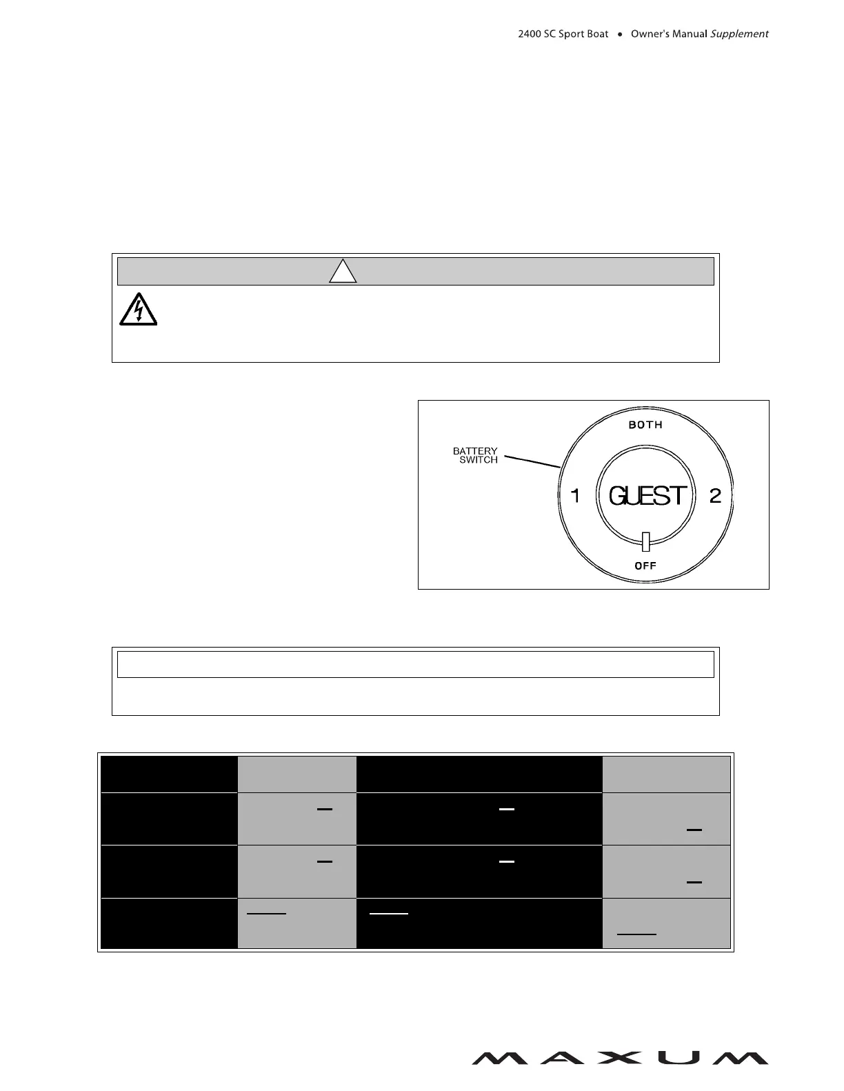
Battery Switch (If Equipped with Two Batteries)
• Standby-loads, such as the automatic bilge pumps
and the stereo memory, are not affected by the battery
switch since they are wired directly to the batteries
(see the Wiring Diagrams section of this chapter for
more details).
• Turn the battery switch to the Off position whenever
your boat will be unoccupied for long periods of time.
Battery Switch Positions
BATTERY SWITCH
POSITIONS
ENGINE
STARTING
ACCESSORIES & LIGHTS
ENGINE
ALTERNATOR
POSITION
1
Battery 1
provides
starting power
Battery 1
provides power for
accessories and lights
Charges
battery 1
POSITION
2
Battery 2
provides
starting power
Battery 2
provides power for
accessories and lights
Charges
battery 2
BOTH
POSITION
BOTH batteries
Provide
starting power
BOTH batteries provide power for
accessories and lights (not advised
unless engine is running)
Charges
BOTH
batteries
SHOCK and ELECTRICAL SYSTEM DAMAGE HAZARD!
When the engine is running, NEVER turn Off the battery switch or disconnect the bat-
tery cables. Doing either could cause damage to your boat’s engine and/or electrical
system components.
CAUTION
!
Since your boat’s batteries were installed by your dealer, the battery switch positions listed
below may vary. Make sure your selling dealer fully explains how to use the battery switches.
NOTICE
 Loading...