This manual provides the description of
using the Digital Clamp Meter safely. Pleas-
se, read and follow the safety information.
To get the best service from this Meter, read
carefully this user’s manual and respect the
detailed safety precautions. Use the meter
only as specied in this manual; otherwise,
the protection provided by the meter may
be impaired. Hereafter, misuse can cause da-
mage or error.
Please, read and follow the safety informa-
tion carefully before usage.
When using the instrument, the user must
observe all normal safety rules:
Never measure higher values than the given
thresholds.
Do not use the Meter around explosive gas,
vapour or dust.
Only use the test probes supplied with the
instrument. Before use, check that they are in
good condition. Never use the instrument if
any of the parts are damaged, or if the instru-
ment and/or your hand is wet.
Never open the battery holder during mea-
suring process.
Do not alternate the function switch during
measuring processes.
Do not use spare-parts to change any da-
maged parts of the Clamp Meter. When re-
pairing the device, always use parts recom-
mended by the manufacturer.
Before changing batteries, always switch o
the instrument and disconnect it from the
circuit.
Never change the batteries in wet conditions
or environment.
Before measuring processes, make sure
about the proper position of the function se-
lection switch.
Do not store the Meter in high temperature
or high humidity and dustful environment
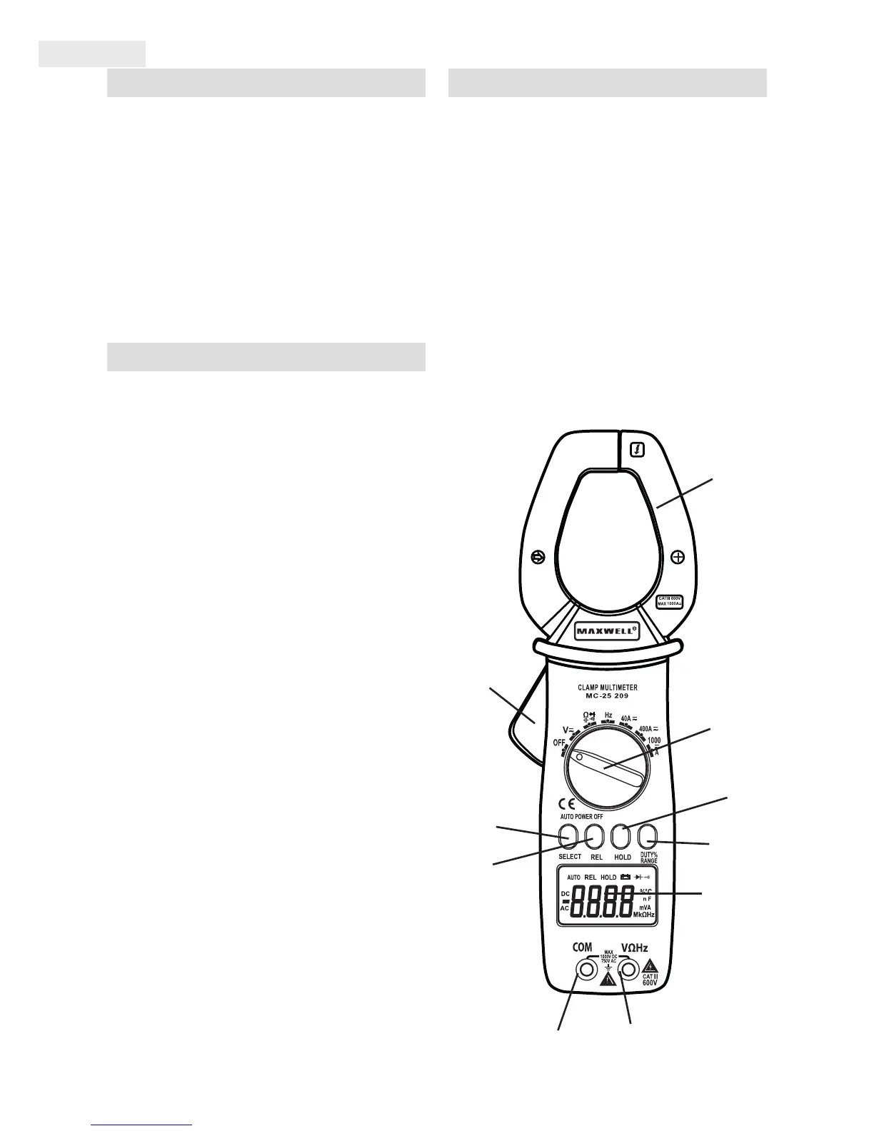
1. Clamp Release Button (opener)
2. Data HOLD Button
3. SELECT Button (Function Selector switch)
4. REL (relative measurement) Switch
5. RANGE/DUTY switch (selection function
and range)
6. COM connector (for connecting the black/
negative measuring wire)
7. V, Ω, CAP, Hz connector (for connecting the
red/positive measuring wire)
8. LCD Display
9. Function/Measuring selection button
10. Measuring Clamps
8.
7.
5.
2.
9.
10.
1.
4.
3.
6.
 Loading...