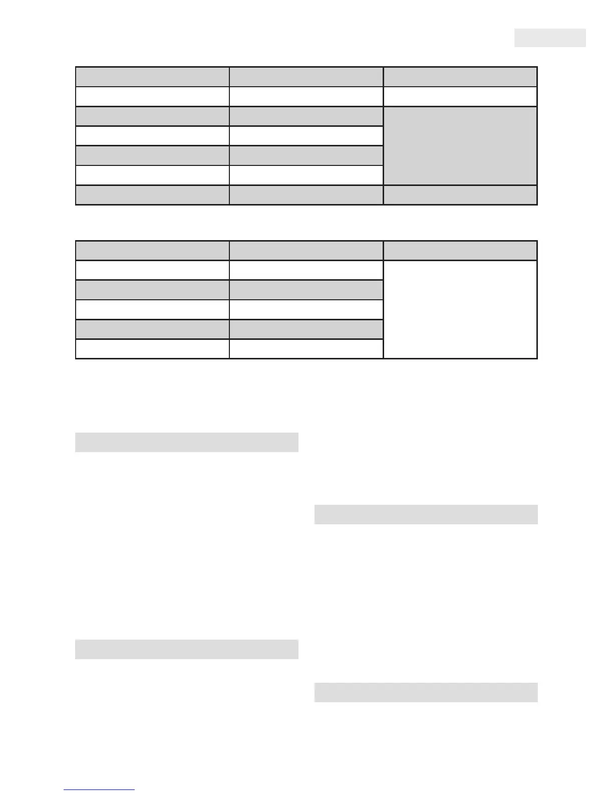
CAPACITANCE
Range Resolution Accuracy (%)
4nF 0.001nF ± (3.5% + 30 digit)
40nF 0.01nF
± (3.0% + 5 digit)
400nF 0.1nF
4μF 0.001μF
40μF 0.01μF
100μF 0.1μF ± (5.0% + 10 digit)
FREQUENCY
Range Resolution Accuracy (%)
9,999Hz 0.001Hz
± (1.5% + 2 digit)
99,99Hz 0,01Hz
999,9Hz 0,1Hz
9,999kHz 1Hz
99,99kHz 10Hz
Input Voltage Range: min. 2V RMS
Overload Protection: 250V DC or AC maximum
1.: Set rotary switch to the „1000A, 400A” or
„40A” position then select the voltage type
(AC or DC) by pushing the „SELECT” button.
Press the trigger to open the transformer
jaws and clamp onto one conductor only.
NOTE: During current measurement, keep
the transformerjaws fully closed. Otherwise,
accurate measurement cannot be made.
Warning: Do not make current measurement
with the test leads connected to the instru-
ment.
Set the rotary switch to the „V” range then by
the „SELECT” button select the voltage type,
DC or AC voltage.
Connect the black and red test leads to the
„COM” and „VΩHz” terminals.
Connect the test leads to the circuit being
measured.
Read the displayed value on the instrument’s
screen.
Set the rotary switch to the „Ω” range.
Connect the black and red test leads to the
„COM” and „VΩHz” terminals.
Connect the test leads to the circuit being
measured.
Read the displayed value on the instrument’s
screen.
WARNING: Always make sure that the circuit
under test is powered o.
Set the rotary switch to „- | | -” range.
Connect the black test leads to the „COM”
 Loading...