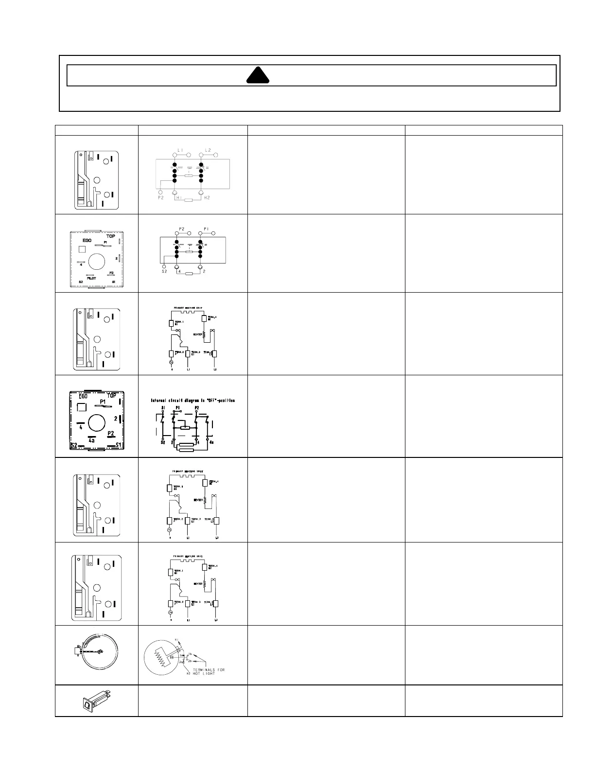
Component Testing Procedures
!
WARNING
To avoid risk of electrical shock, personal injury or death; disconnect power to range before servicing, unless
testing requires power.
June 2006 16027233
© 2006 Maytag Services Replaces 16027002
3
Illustration Component Test Procedure Results
(MER5875RC*)
L2
L1
H2
P
H1
1
2
3
4
5
Infinite switch
Remove wiring from H1 and H2.
Connect volt/ohms meter to H1 and H2.
Measure the following for voltages at
LO, MED, HI: ...........................................
Voltage between H1 and H2....................
Approximate
Time On Time Off
LO 5% 95%
MED (4-5) 35% 65%
HI 100% 0%
240 VAC. If not, replace switch.
(MER5875RC*)
Infinite switch
Remove wiring from 2 and 4. Connect
volt/ohms meter to 2 and 4.
Measure the following for voltages at
LO, MED, HI: ...........................................
Voltage between 2 and 4 .........................
Approximate
Time On Time Off
LO 5% 95%
MED (4-5) 35% 65%
HI 100% 0%
240 VAC. If not, replace switch.
(MER5875RC*)
L2
L1
H2
P
H1
1
2
3
4
5
Infinite switch, low heat
Remove wiring from H1 and H2.
Connect volt/ohms meter to H1 and H2.
Measure the following for voltages at
LO, MED, HI: ...........................................
Voltage between H1 and H2....................
Approximate
Time On Time Off
SIMMER 5% 95%
MED (5) 55% 45%
HI 100% 0%
240 VAC. If not, replace switch.
(MER5875RC*)
Infinite switch, dual
element
Remove wiring from H1 and H2.
Connect volt/ohms meter to H1 and H2.
Measure the following for voltages at
LO, MED, HI: ...........................................
Voltage between H1 and H2....................
Approximate
Time On Time Off
LO 8% 92%
MED (4-5) 35% 65%
HI 100% 0%
240 VAC. If not, replace switch.
(AER5815RC*)
L2
L1
H2
P
H1
1
2
3
4
5
Infinite switch
Remove wiring from H1 and H2.
Connect volt/ohms meter to H1 and H2.
Measure the following for voltages at
LO, MED, HI: ...........................................
Voltage between H1 and H2....................
Approximate
Time On Time Off
LO 5% 95%
MED (4-5) 35% 65%
HI 100% 0%
240 VAC. If not, replace switch.
Ribbon element, 1200 W
Disconnect wiring to element and
measure cold resistance of terminals ......
Measure voltage at element ....................
Approx. 44.3 to 48.9 Ω.
240 VAC. If voltage is not present,
check wiring.
Backguard outlet circuit
breaker
Measure continuity between terminals:
Switch reset (closed) ...............................
Switch not reset (open)............................
Push-to-Reset.
Continuity.
Infinity.
 Loading...