Do you have a question about the Maytag MVWB850WQ and is the answer not in the manual?
Warning about disconnecting power before servicing to prevent death or shock.
Guidance on handling ESD sensitive electronic components to prevent damage.
Checks to perform before servicing, including power, fuses, and water supply.
Steps to activate the automatic diagnostic test mode by pressing specific buttons.
Procedure for running the automatic 5-minute diagnostic test for washer functions.
Troubleshooting for when diagnostic mode entry fails, with specific indications and actions.
How saved fault codes are displayed and accessed within diagnostic mode.
Steps to activate manual diagnostic mode by pressing buttons after automatic mode entry.
Procedure to test the washer's water inlet valves for fresh, detergent, softener, bleach, and oxi.
Procedure to test the washer's recirculation and drain pumps.
Procedure to test the washer's lid lock mechanism and switch.
Procedure to test the motor, including rotor position sensor and spin/agitate functions.
Procedure to test the washer's heater element, if equipped.
Steps to activate the diagnostic test for console buttons, indicators, and display.
Indicates water level not changing or not detected by control.
Indicates water level not changing after drain pump activation.
Indicates an off-balance load detected by the control.
Indicates a load size exceeding capacity or basket disengagement failure.
Indicates a suds-lock condition detected by the control.
Indicates issues with lid switch detection or user interaction.
Indicates drain pump activation due to lid left open.
Indicates inlet hoses are connected incorrectly.
Indicates failure of the lid to lock completely.
Indicates failure of the lid to unlock.
Indicates control detects an out-of-range pressure signal.
Indicates a stuck key or internal UI problem.
Indicates communication failure between CCU and UI.
Indicates ATC thermistor is open or shorted.
Indicates motor RPS thermistor is open or shorted.
Indicates control cannot detect heater ON/OFF status.
Indicates heater is ON when it should be OFF.
Indicates heater is ON but control cannot detect it.
Indicates motor rotor position sensor detects no rotation.
Indicates motor RPS failure or harness problem.
Indicates motor RPS senses rotation after stop command.
Indicates high temperature detected for the motor module.
Indicates high current detected for the motor module.
Indicates failure to determine basket re-engagement after disengagement.
Troubleshooting steps for when the washer does not respond to button presses.
Troubleshooting steps for when the START/PAUSE button does not initiate a cycle.
Troubleshooting for when the control does not accept input selections.
Troubleshooting steps for when the washer does not dispense water or detergent.
Troubleshooting steps for when the washer fails to fill with water.
Troubleshooting steps for when the washer overfills with water.
Troubleshooting steps for when the washer does not agitate.
Troubleshooting steps for when the washer does not spin.
Troubleshooting steps for when the washer fails to drain.
Troubleshooting for incorrect water temperature during cycles.
Troubleshooting for when all fills result in hot water.
Troubleshooting for when the washer does not recirculate water.
General guidance for flashing displays, referring to fault codes.
Procedure to reset cycle settings to factory defaults.
Checks electrical connections to the machine/motor control and power cord continuity.
Tests electrical connections to water valves and valve resistance.
Checks wiring to motor and RPS, and tests motor and RPS components.
Tests console electronics, indicators, buttons, and beep sound functionality.
Checks water inlet valves, temperature sensor, and machine/motor control for temperature accuracy.
Tests water level sensing components and calibrates the pressure sensor.
Checks pump motor windings and connections for drain/recirculation failures.
Checks lid lock motor winding, switches, and resistance for lock/unlock failures.
Checks heater element resistance and connection to the heater relay board.
Troubleshoots communication issues between the UI and machine/motor control.
Steps for accessing the machine/motor control and user interface assemblies.
Procedure for removing the machine/motor control assembly from the console tray.
Procedure for removing the user interface printed circuit assembly board.
Guidance for reinstalling the user interface printed circuit assembly board.
Diagram showing electrical connections between components like motor, pumps, valves, and controls.
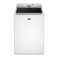
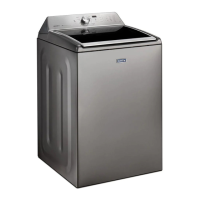
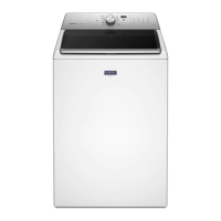
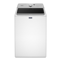
| Brand | Maytag |
|---|---|
| Model | MVWB850WQ |
| Type | Top Load Washer |
| Capacity | 4.3 cu. ft. |
| Color | White |
| Energy Star Certified | Yes |
| Wash Cycles | 11 |
| Control Type | Electronic |
| Depth | 27 in |
| Agitator | Yes |
| Spin Speed | 700 RPM |
| Width | 27 in |

 Loading...