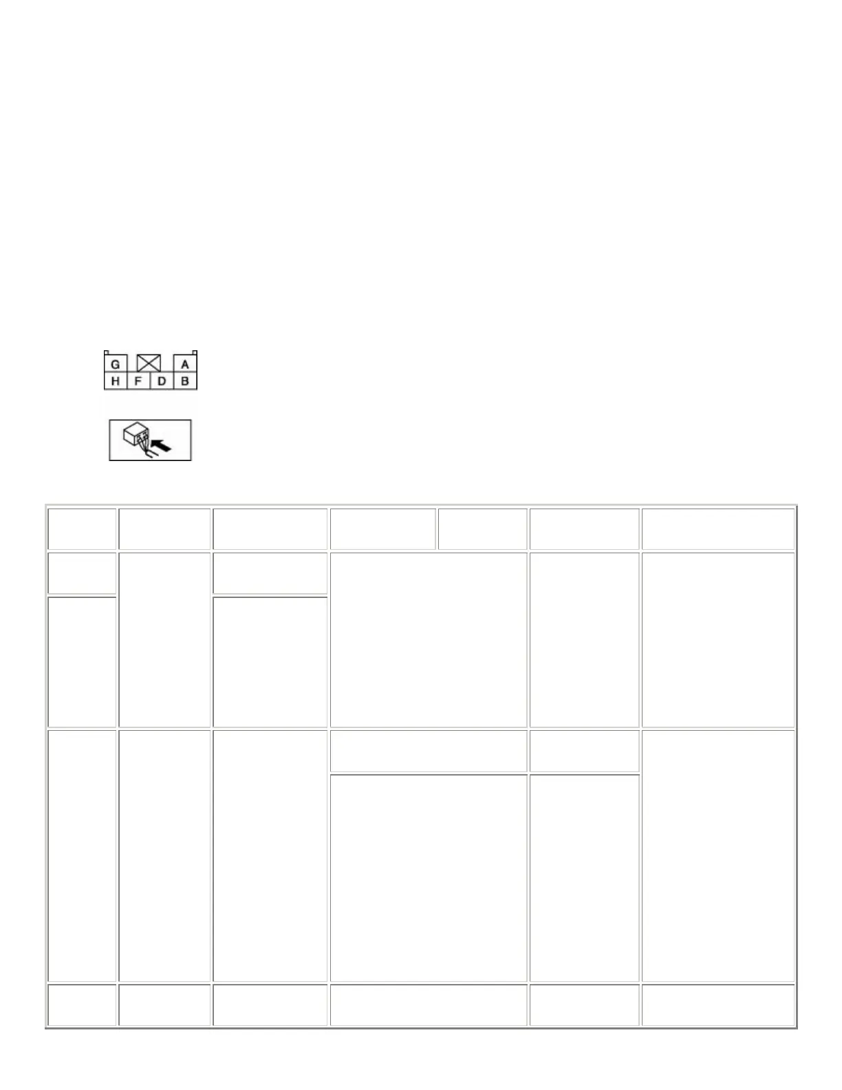
4. Disconnect the panel light control switch connector.
5. Verify that continuity at terminal D is as indicated in the Terminal Voltage Table (Reference).
• If there is any malfunction, inspect the parts under "Inspection item(s)".
If the system does not work properly even though the parts or related wiring harnesses do
not have any malfunction, replace the panel light control switch.
Terminal Voltage Table (Reference)
Terminal Signal name Connected to
Measured
condition
Measured
condition
Voltage
(V)/Continuity
Inspection item(s)
A
Instrument
cluster
F
Illumination
Each
illumination
Inspect using an
oscilloscope. (See Terminals
A and F Inspection .)
−
• Instrument
cluster
• Each
illumination
• Related wiring
harnesses
Turn the light switch to the
TNS or ON position.
B+
B TNS TNS relay
Turn the light switch to the
OFF position.
1.0 or less
• TNS relay
(See RELAY
INSPECTION
.)
• ILLUMI 10 A
fuse
• Related wiring
harnesses
D GND Body ground
Under any condition:
Ins
ect for continuit
to
Continuity
detected