EasyManua.ls Logo

MB QUART MBQ-CAM-1 - User Manual

MB QUART MBQ-CAM-1
2 pages
Print Icon
To Next Page IconTo Next Page
Loading...
CAUTION
Always consider consulting a professional installer before installing
any components. Be careful and take your time. Do not let wires
make contact with metal edges or hot engine components.
Congratulations on your choice of a MB Quart Auxiliary
Camera. This “Quick Start” Installation guide is meant to
help you complete a basic installation. Visit our website at
MBQuart.com for more detailed information.
Disconnect the negative battery terminal from the negative battery post
before installing.
MOUNTING LOCATION
Locate your desired switch and camera location. Mount the switch in
an open carling knockout. If you do not have an open carling knockout,
the unit itself requires a 0.83 inch (21mm) wide by 1.4 inch (37mm)
high opening with at least 2.5 inches of clearance behind the mounting
surface.
WIRE ROUTING
Route wiring labeled P2,P3,P7 to the switch location.
Route purple reverse wire and yellow RCA video cables to the
source unit/display.
Route white 4 pin JST connector to the camera
mounting location.
Route 12v, ACC, and GND wires to the vehicle battery or buss bar.
CAMERA FLUSH MOUNTING
The camera comes with the ush mount already attached
(shown below). If your install location doesn’t allow for ush mounting,
please see surface mounting instructions on page 2.
To ush mount the camera, use the supplied 18.5mm hole saw to drill
the hole, making sure there is adequate room behind the panel.
Camera/Switch Installation
CAMERA SURFACE/BRACKET MOUNTING
To surface mount the camera, using the supplied bracket, unscrew
the ush mount trim ring that comes on the camera. Next, screw
on the surface mount bracket. Secure the bracket to the mounting
location you have chosen.
Note - may need to attach bracket to vehicle panel prior to attaching to camera.
WIRING CONNECTIONS
Connect the white 4pin JST from the camera to the camera harness.
At this time you will connect the yellow RCA to the camera input of
your source unit or GMR7V1. Connect your camera’s reverse wire to
the camera trigger input on the radio. (See wiring diagram on page 4)
After all this is done, you can now connect the +12v, ACC, and GND
wires to the buss bar or battery and reconnect the negative battery
terminal to the negative battery post.
Camera/Switch Installation
REVERSE CAMERA ONLY
If using as a reverse camera only - cut the loop (green wire) located
on the camera wiring. Then connect the reverse wire to the reverse
trigger wire of your source unit to activate as a reverse camera.
Features
IPX Rating
Horizontal Angle
Vertical Angle
Image Sensor
Optical Format
Signal Noise Ratio
Input Voltage
Mirror or Real Image
Parking Line
LED
EMC
IPX67/IP69K
150 °
170 °
1/3 ″ CMOS
NTSC
>48dB (AOC On)
12V DC
Both (Cut Loop)
NONE
NONE
RE-10
3 of 4
Question and Answer IconNeed help?

Do you have a question about the MB QUART MBQ-CAM-1 and is the answer not in the manual?

Overview

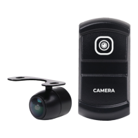
The MBQ-CAM-1 is an auxiliary camera designed to enhance vehicle safety and convenience, primarily functioning as a reverse camera but also offering flexibility for other viewing applications. It is engineered to integrate with a vehicle's existing display or source unit, providing a visual feed of the area behind or around the vehicle.

Function Description:

The primary function of the MBQ-CAM-1 is to provide a visual aid for drivers, particularly when reversing. When configured as a reverse camera, it can be activated automatically by connecting its reverse wire to the vehicle's reverse trigger input. The camera captures video footage and transmits it via an RCA video cable to a compatible display unit, such as a car stereo with a camera input or a dedicated monitor like the GMR7V1.

The camera offers two main mounting options: flush mount and surface mount. The flush mount option provides a sleek, integrated look, requiring an 18.5mm hole to be drilled into the mounting panel. The camera comes with a flush mount trim ring pre-attached, which can be removed for surface mounting. For surface mounting, a supplied bracket is used, allowing the camera to be screwed onto a flat surface.

The system includes a switch, which can be mounted in an open carling knockout. This switch allows for manual control of the camera, potentially enabling its use for applications beyond just reversing, such as monitoring a specific area around the vehicle while driving. The switch requires an opening of 0.83 inches (21mm) wide by 1.4 inches (37mm) high, with at least 2.5 inches of clearance behind the mounting surface.

The camera's wiring harness facilitates connection to the vehicle's electrical system. Key connections include:

  • P2, P3, P7 wires: Routed to the switch location.
  • Purple reverse wire: Connects to the camera trigger input of the source unit/display for automatic activation when reversing.
  • Yellow RCA video cable: Connects to the camera input of the source unit/display to transmit video.
  • White 4-pin JST connector: Connects the camera unit to the main harness.
  • +12V, ACC, and GND wires: Connect to the vehicle's battery or buss bar for power.

For users who only intend to use the camera as a reverse camera, a green wire loop on the camera wiring can be cut. This configuration simplifies the setup for dedicated reverse camera functionality. The camera is designed to provide both mirror and real image options, with the ability to switch between them by cutting a loop, although the manual indicates "Both (Cut Loop)" for this feature. It does not include parking lines or LED illumination, simplifying its design and potentially reducing power consumption.

Important Technical Specifications:

  • IPX Rating: IPX67/IP69K – This indicates a high level of protection against dust and water ingress, making it suitable for outdoor and marine environments. IP67 means it is dust-tight and can withstand immersion in water up to 1 meter for 30 minutes. IP69K signifies protection against close-range high-pressure, high-temperature spray downs, which is particularly relevant for vehicle washing.
  • Horizontal Angle: 150° – Provides a wide field of view horizontally, crucial for comprehensive coverage behind or around a vehicle.
  • Vertical Angle: 170° – Offers an even wider vertical field of view, helping to capture objects close to the ground as well as those further away.
  • Image Sensor: 1/3" CMOS – A common type of image sensor known for good image quality and low power consumption.
  • Optical Format: NTSC – The standard analog television system used in North America, ensuring compatibility with most vehicle displays in the region.
  • Signal Noise Ratio (SNR): >48dB (AOC On) – A higher SNR indicates a cleaner image with less background noise, especially when Automatic Optical Control (AOC) is active.
  • Input Voltage: 12V DC – Standard vehicle electrical system voltage.
  • Mirror or Real Image: Both (Cut Loop) – Allows the user to select between a mirrored image (typical for reverse cameras) and a real image, depending on the installation and preference.
  • Parking Line: NONE – The camera does not overlay parking lines directly onto the video feed.
  • LED: NONE – The camera does not feature built-in LED illumination.
  • EMC: RE-10 – Indicates compliance with electromagnetic compatibility standards, ensuring it does not interfere with other vehicle electronics.
  • Switch Opening Dimensions: 0.83 inches (21mm) wide x 1.4 inches (37mm) high.
  • Flush Mount Hole Saw Size: 18.5mm.

Usage Features:

  • Versatile Mounting: Supports both flush and surface mounting, offering flexibility for different vehicle types and aesthetic preferences.
  • Reverse Camera Functionality: Can be configured for automatic activation when the vehicle is put into reverse, providing immediate visual feedback.
  • Manual Control: The included switch allows for manual activation, enabling the camera to be used for continuous monitoring or on-demand viewing.
  • Wide Field of View: The 150° horizontal and 170° vertical angles provide extensive coverage, reducing blind spots.
  • Durable Design: IPX67/IP69K rating ensures robust performance in harsh environmental conditions, including exposure to dust, water, and high-pressure washing.
  • NTSC Compatibility: Ensures seamless integration with most standard vehicle display units in regions using the NTSC format.
  • Mirror/Real Image Option: Provides adaptability for various viewing needs, whether for backing up or general monitoring.

Maintenance Features:

  • Robust Construction: The high IPX rating (IPX67/IP69K) indicates that the camera is designed to withstand environmental elements, reducing the need for frequent maintenance related to weather exposure.
  • Secure Connections: The installation instructions emphasize ensuring all wiring and connections are secure and away from moving parts or extremely hot surfaces. Proper installation minimizes the risk of damage or malfunction due to vibration or heat.
  • FCC Compliance: The device complies with FCC rules, which implies it is designed to operate without causing harmful interference and is built to certain quality standards.
  • Warranty: Maxxsonics, LLC. provides a one-year warranty from the date of purchase, covering defects in material and workmanship. This offers peace of mind and support for potential manufacturing issues.
  • Professional Installation Recommendation: The manual advises consulting a professional installer, which can help ensure correct installation and potentially extend the life of the device by avoiding common installation errors.
  • Website Support: Users are directed to MBQuart.com for more detailed information and support, indicating resources are available for troubleshooting and maintenance guidance.

MB QUART MBQ-CAM-1 Specifications

General IconGeneral
BrandMB QUART
ModelMBQ-CAM-1
CategoryDigital Camera
LanguageEnglish