- 8 -
SERVICE
Assembly and disassembly should be performed by a
service technician who has been factory trained on MBW
equipment. The unit should be clean and free of debris.
Pressure washing before disassembly is recommended.
• Prior to assembly, wash all parts in a suitable cleaner or
solvent.
• Check moving parts for wear and failure. Refer to the
Replacement section in this manual for tolerance and
replacement cycles.
• All shafts and housings should be oiled prior to pressing
bearings. Also, ensure that the bearings are pressed
square and are seated properly.
• All bearings should be replaced when rebuilding any
exciter or gearbox.
• All gaskets and seals should be replaced after any
disassembly.
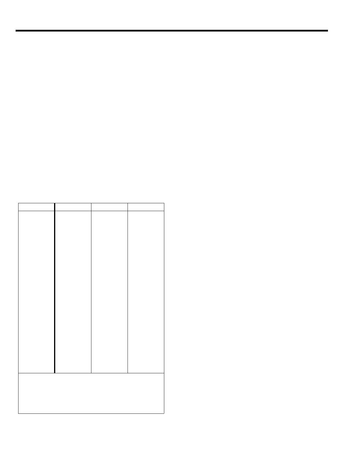
Torque Chart
Exciter Disassembly
Steps 1 thru 6 reference the figure on page 12.
1. Remove the belt guard (#5) and v-belt (page 18, #3).
2. Remove the bolts (#29) that hold the deck (#2) to the
housing (#1).
3. Lift entire deck with engine from housing.
4. Remove the four exciter hold down bolts (#18).
5. Lift the exciter (#3) from the housing (#1).
6. Clean the exciter before proceeding with the
disassembly.
Steps 7 thru 17 reference the figure on page 16.
7. Remove the flange screw (#21) and washer (#14)
securing the pulley (#3) to the exciter shaft (#2).
8. Slide the pulley off the exciter shaft. Be careful not to
lose the key (#15).
9. Remove rear cover (#5) by unscrewing the six flange
screws (#21).
10. Block exciter housing (#1) on large O.D. side (rear
cover side), then press exciter shaft through exciter
housing.
11. Remove front cover (#4) by unscrewing the six flange
screws (#20).
12. Remove bearing (#12) from exciter housing by
pressing it out from the inside.
13. Remove retainer (#7) by unscrewing the two cap
screws (#19).
14. Remove snap ring (#8).
15. Remove bearing (#11) from rear cover (#5) by using
a 1/4” punch. Tap the bearing out thru the holes from
the cap srews in step 13. Be sure to alternate
between holes to avoid cocking the bearing.
16. Remove snap ring (#9).
17. Remove inner race of bearing (#11) from the exciter
shaft by supporting the O.D. of the race and pressing
the exciter shaft thru.
Exciter Assembly
Steps 1 thru 19 reference the figure on page 16.
1. Press bearing (#12) into exciter housing (#1). Use
care to press on the O.D. of the bearing only.
2. Press the inner race of bearing (#11) onto exciter
shaft (#2).
3. Install snap ring (#9) onto exciter shaft.
SIZE GRADE 2 GRADE 5 GRADE 8
1/4-20 49 in
•lbs 76 in•lbs 9 ft•lbs
1/4-28 56 in
•lbs 87 in•lbs 10 ft•lbs
5/16-18 8 ft
•lbs 13 ft•lbs 18 ft•lbs
5/16-24 9 ft
•lbs 14 ft•lbs 20 ft•lbs
3/8-16 15 ft
•lbs 23 ft•lbs 33 ft•lbs
3/8-24 17 ft
•lbs 26 ft•lbs 37 ft•lbs
7/16-14 24 ft
•lbs 37 ft•lbs 52 ft•lbs
7/16-20 27 ft
•lbs 41 ft•lbs 58 ft•lbs
1/2-13 37 ft
•lbs 57 ft•lbs 80 ft•lbs
1/2-20 41 ft
•lbs 64 ft•lbs 90 ft•lbs
9/16-12 53 ft
•lbs 82 ft•lbs 115 ft•lbs
5/8-11 73 ft
•lbs 112 ft•lbs 159 ft•lbs
5/8-18 83 ft
•lbs 112 ft•lbs 180 ft•lbs
3/4-16 144 ft
•lbs 200 ft•lbs 315 ft•lbs
1-8 188 ft
•lbs 483 ft•lbs 682 ft•lbs
1-14 210 ft
•lbs 541 ft•lbs 764 ft•lbs
1-1/2-6 652 ft
•lbs 1462 ft•lbs 2371 ft•lbs
M 6 3 ft
•lbs 4 ft•lbs 7 ft•lbs
M 8 6 ft
•lbs 10 ft•lbs 18 ft•lbs
M 10 10 ft
•lbs 20 ft•lbs 30 ft•lbs
CONVERSIONS
in
•lbs x 0.083 = ft•lbs
ft
•lbs x 12 = in•lbs
ft
•lbs x 0.1383 = kg•m
ft
•lbs x 1.3558 = N•m


 To Next Page