With the Bypass Switch in place, normal Sensor operation supplies power to the switch through a control cable.
While the Sensor is operating, the switch is "on" and routes all trac directly through the Sensor. When the
Sensor fails, the switch automatically shifts to a bypass state: in-line trac continues to ow through the
network link, but is no longer routed through the Sensor. Once the Sensor resumes normal operation, the
switch returns to the "on" state, once again enabling in-line monitoring.
Note that Sensor outage breaks the link connecting the devices on either side of the Sensor for a brief moment
and requires the renegotiation of the network link between the two peer devices connected to the Sensor.
Depending on the network equipment, this disruption introduced by the renegotiation of the link layer between
the two peer devices may range from a couple of seconds to more than a minute with certain vendors' devices.
A very brief link disruption may also occur while the links between the Sensor and each of the peer devices are
renegotiated to place the Sensor back in in-line mode. This outage, again, varies depending on the device, and
can range from a few seconds to more than a minute.
Installation and troubleshooting instructions for the Kit can be found in the Guide that accompanies the kit. For
example, for more information on the Optical kit, see the standard Gigabit Optical Fail-Open Bypass Kit Guide.
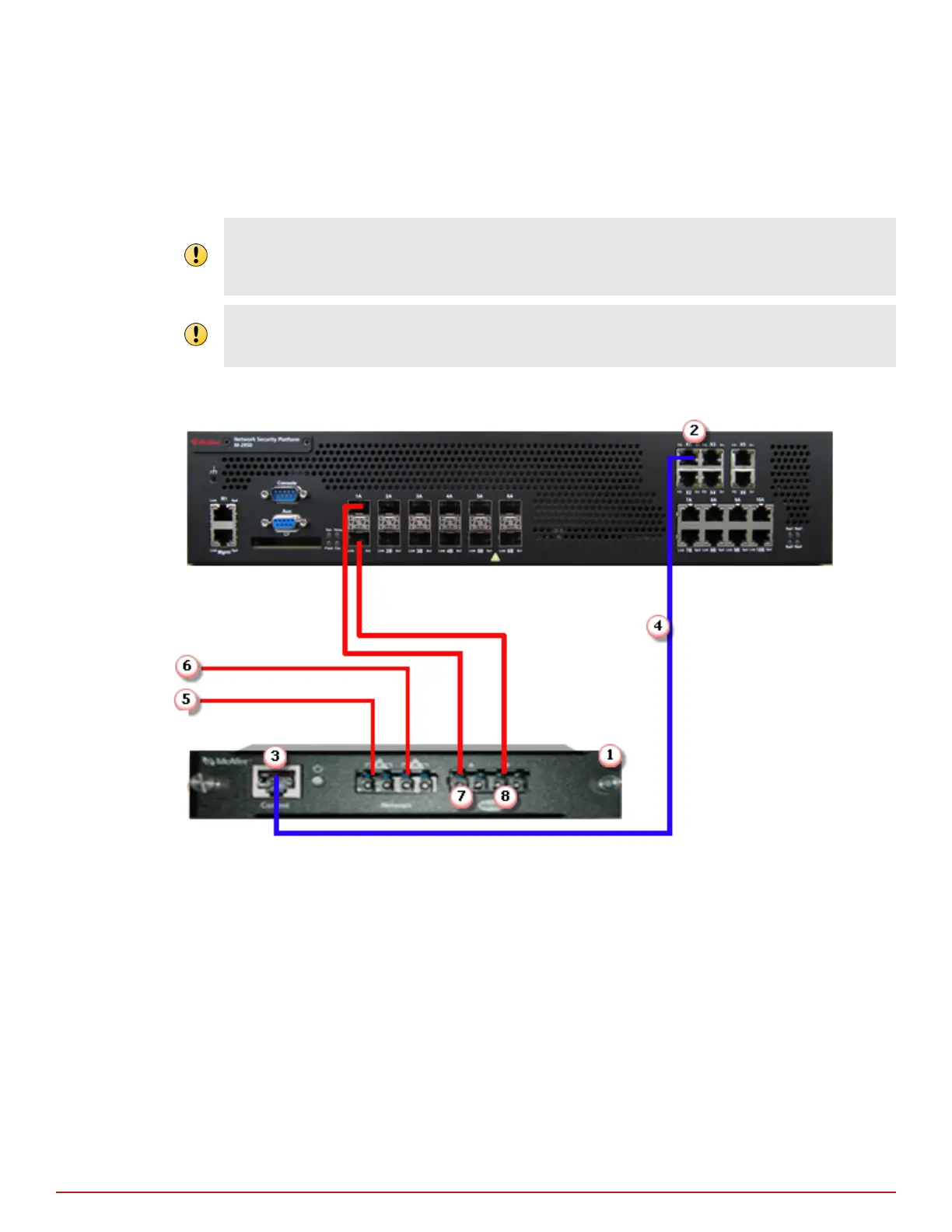
Figure 4-3 Fail-open switch connected to ports 1A-1B
4
Attaching cables to the Sensor
About the fail-open hardware
28
McAfee
®
Network Security Platform M-2850/M-2950 Sensor Product Guide