2-- 1
© 2012 Mobile Climate Control T-299 Rev. 08/2012
SECTION 2
OPERATION
2.1 OPERATING INSTRUCTIONS
Before attempting to operate the system, power
must be available from the vehicle battery. If the
engine is not running, start the engine.
The system may be supplied with Manual Controls
(see Figure 2-1 & Figure 2-3 ) or the Mobile Climate
Control Total Control (see Figure 2-5).
Refer to the Sections 2.2 & 2.3 for manual control
operating instructions or Section 2.5 for Total
Control operating instructions.
2.2 MANUAL CONTROLS
Mobile Climate Control systems are manually
operated by a Drivers Control Panel (See Figure 2-1)
wired into an Electrical Control Panel (See
Figure 2-2).
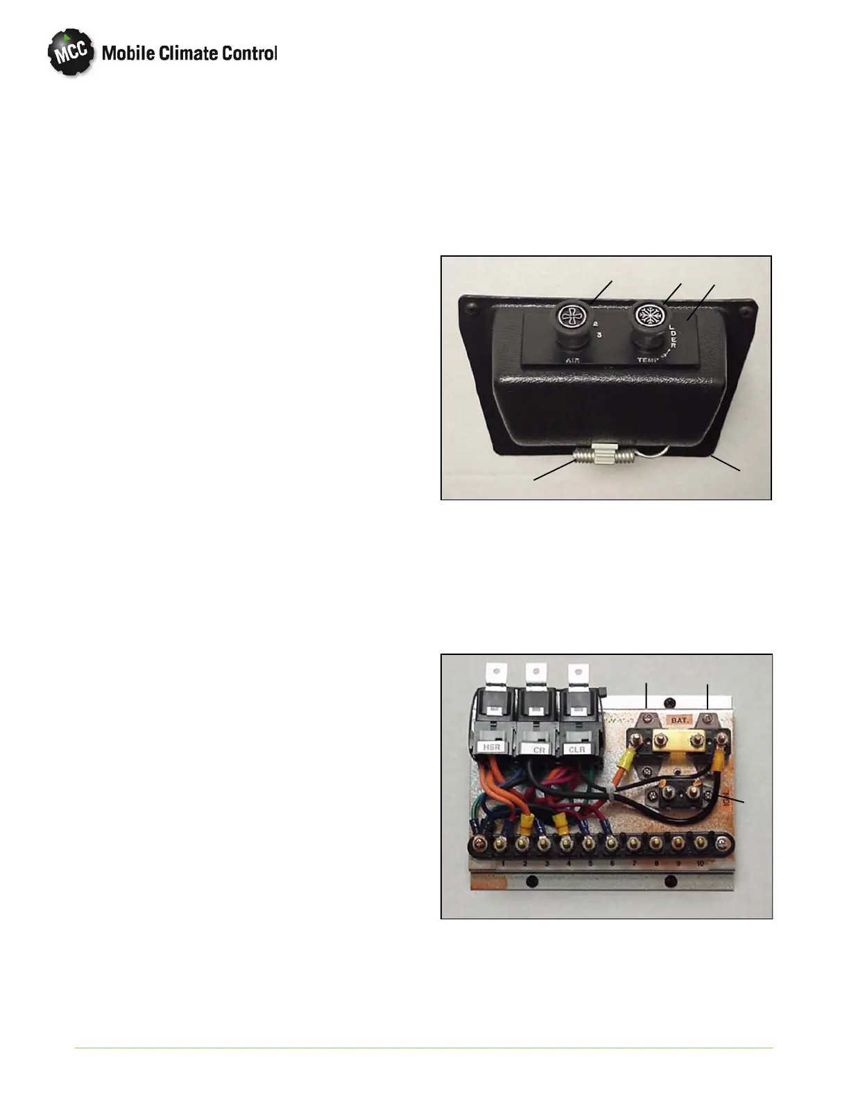
2.2.1 Driver's Control Panel
The Drivers Control Panel (See Figure 2-1), consists
of an evaporator fan speed switch (three speed or
variable) and an adjustable thermostat. The drivers
control panel is normally located within easy reach of
the driver. On larger bus applications there could be
two (2) separate air conditioning system driver
contro l panels. One for each system.
There will be some applications where the switch
mounting plate, thermostat and fan speed switch are
mounted in the drivers area without the control
panel housing.
On some applications the vehicle manufacturer
(OEM) will supply different type controls for the air
conditioning system. Refer to OEM technical
manual for operating instructions.
2.2.2 Fan Speed Switch (three speed or variable)
Three Speed - Th e standard fan speed switch has
four settings, Off (0), Low (1), Medium (2), and High
(3) speed operation. This switch controls the
operation of the system and the evaporator
blower(s) by energizing the appropriate circuits and
relays located on the electrical control panel. See
Figure 2-2.
Variable Speed - Certain applications may be fitted
with a variable speed control switch instead of the
standard three speed switch. This switch controls the
speed of the evaporator motors by varying the
supply voltage.
2.2.3 Thermostat Control
The thermostat controls the temperature within the
passenger co m p artment b y switching system
components on and off.
1
234
5
1 Control Panel Housing
2 Nameplate (Switch Mounting)
3 Thermostat Control Switch
4 Fan Speed Switch (3 Speed or Variable)
5 AmbientAirSensor(Thermostat)
Figure 2-1 Drivers Control Panel
2.2.4 Electrical Control Panel
The electrical control panel contains relays and
circuit breakers used for system control.
1
2
3
4
5
6
1 High Speed Relay
2 Condenser Relay
3 Compressor Clutch Relay
4 Circuit Breaker (HSR)
5 Circuit Breaker (CR)
6 Circuit Breaker (Ignition)
Figure 2-2 Electrical Panel (Typical)

 Loading...