2-- 2
© 2012 Mobile Climate Control T-299 Rev. 08/2012
2.3 FLORIDA CONTROL (TEMPCON)
This controller is normally used in school buses
located within the state of Florida, but not limited to
that area (See Figure 2-3). This cont roller is wired to
an electrical control b o ard.
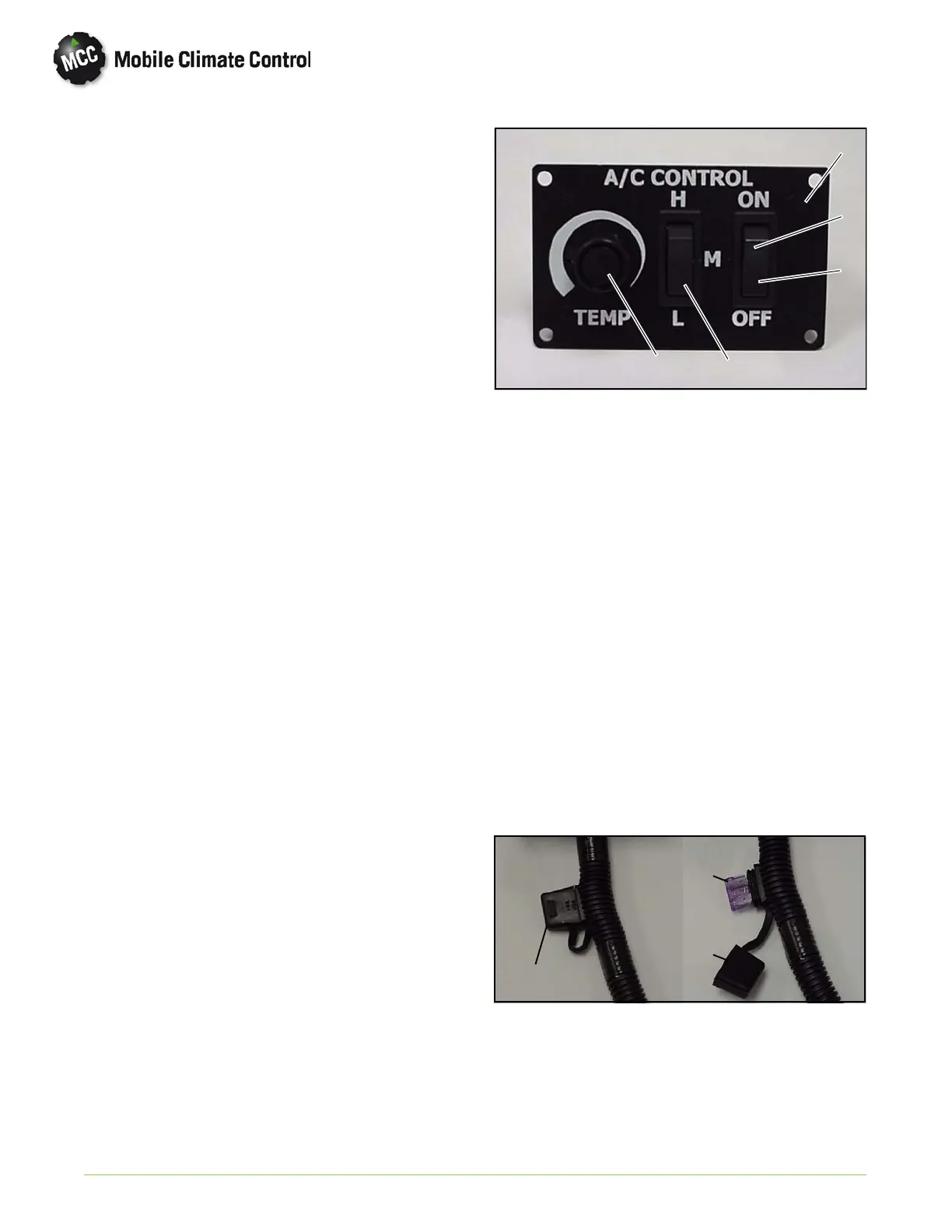
The controller consists of:
a. ON/OFF Switch
b. Fan Speed Switch
c. Potentiometer
d. In-Line Fuse (Behind Controller)
2.3.1 ON/OFF Function
Power is supplied to the controller, through an
in-line fuse (see Figure 2-4) from a 12 VDC ignition
source originating from the vehicle. The controller
will not operate until the ignition switch is activated.
Move the ON/OFF switch to the ON position. A
green light will illuminate indicating that the
controller has power. At the same time the
evaporator fans will operate in either Low, Medium
or High speed, depending on th e Fan Speed switch
position.
2.3.2 Fan Speed Switch - 3 Speed
The evaporator fan speeds can be adjusted by
pushing the rocker switch to the desired position:
a. H = High Sp eed
b. M = Medium Speed
c. L = Low Speed
When the evaporator fan speed switch is positioned
at th e desired speed, a signal is sent to the
corresponding fan speed relay located on the
electrical circuit board.
2.3.3 Adjusting Set Point (Interior Temperature Adjust-
ment)
The potentiometer switch has an operating range
between 60 and 85 degrees F. (+/- 1 degree F.).
Rotate the potentiometer switch knob to the right
(clockwise) for maximum cooling.
Rotate the potentiometer switch knob to the left
(count erclockwise) for less cooling.
1
2
3
4
5
1FacePlate
2 Green Light)
3 Rocker Switch, 2 Position, ON/OFF
4 Rocker Switch, 3 Position, LOW-MED-HIGH
5 Tempe rature Switch (Potentiometer)
Figure 2-3 Switch Assembly (TEMPCON)
2.4 IN-LINE FUSE (FLORIDA CONTROL)
The controller is protected by a 3 Amp ATO in-line
fuse (Figure 2-4). To replace t he fuse do the
following:
a. Make sure ignition power is off.
b. Grasp fuse cover at finger grips and lift off
cover.
c. Remove fuse and check if fuse is defective.
d. Replace if needed.
e. Push fuse cover back on to in-line holder.
f. Restore ignition power and place ON/OFF
switch to ON.
Fuse
3Amp
In--Line Fuse
& Holder
Fuse
Cover
Figure 2-4 In-Line Fuse & Holder (3 Amp)

 Loading...