2-- 3
© 2012 Mobile Climate Control T-299 Rev. 08/2012
2.5 TOTAL CONTROL
The Total Control system consists of a Key Pad
Display (See Figure 2-5) wired to an Electrical
Control Panel (See Figure 2-7). Refer to Figure 2-5
for the following operating functions.
1
2
3
4
5
68
9
10
11
12
7
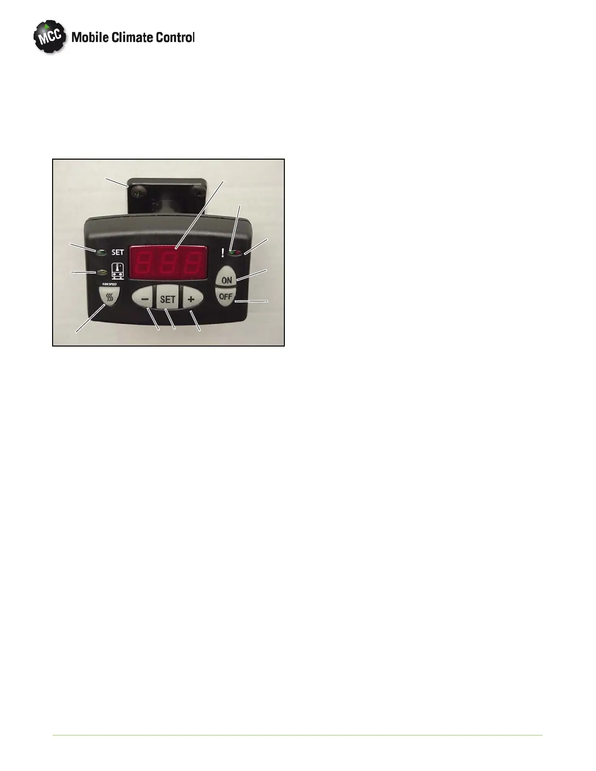
1Display
2 Green LED, Cool Mode
3RedLED,HeatMode
RedLED,Flash,Alarm
4 ON Button
5 OFF Button
6 Increase Selection
7 SET Button
8 Decrease Selection
9 Fan Speed Button
10 Green LED, Inside Temperature
11 Green LED, Set Point
12 Total Control Mounting Assembly
Figure 2-5 Total Control Key Pad/Display
1 ON/OFF Button
Press the ON or OFF button to turn the system on
or off. The display will show the temperature set
point.
2 Return Air Temperature
If SET key is pressed the display will show return air
(inside) temperature. With the inside temperature
displayed, the green led on the left side of the display
(which has the symbolof a bus with a thermalsensor)
will be illuminated. If no key is pressed the display will
go back to show set point after 30 seconds.
3 Adjusting Set Point
To adjust the set point, press the SET button.
The green SET led will illuminate on the left side of
the display.
Press the + o r - keys to bring th e desired set point
into the display.
If the set point is below the inside temperature, the
cooling will come on. This will be characterized by a
green led on the right side at the top of the display.
If the set point is above the inside temperature, heat
will come on. This will be characterized by a red led
on the right side at the top of the display.
4 Adjusting Fan Speed
Press the FAN SPEED button. The present setting
(1 to 10) will show in the display.
Press the + or - button to adjust the fan speed. The
number 10 represents the highest speed and th e
numb er 1 represents the lowest speed.
5Alarms
With the alarm led flashing, the alarm code may be
displayed by pressing the SET button. Refer
Table 3-5 for system alarm code descriptions.
2.5.1 Total Control Operation
1 Control Stages
Temperature control will be regulated using 3 stages
based on the return air temperature.
Cool
Null
Heat
When started, if the return air tem p erature sensor
senses the temperature higher than the set point, the
system will run cooling. When the return air
temperature decreases to lower th an th e set point,
cooling stage will stop and system will be in the null
mode.
When started, if the retu rn air temperature is lower
than the set point, the system will run h eating (refer
to paragraph 2.8.5). When the return air temperature
increases to higher than the set point, heating stage
will stop and system will be in null mode.
In the null m ode, if return air temperature increases
to be out of the null band, system will run heating. If
return air temperature decreases to be out of the null
mode, system will run heating. The center of the nu ll
band is the set point and the width of the null band is
controlled by m icroprocessor parameter P01.
For example, if the null band is 4 F and set point is
72° F, system will run cooling if temperature is higher
than 72 + 2 = 74. System will run heating if
temperature is lower than 72 - 2 = 70.
 Loading...
