2-- 9
© 2012 Mobile Climate Control T-299 Rev. 08/2012
Fan speeds can be controlled manually by pressing
the Vent Key (Item 2 in Figure 2-8), an LED light
will activate in the corner of the Vent Key . After
pressing th e Vent Key, use the Increase/Decrease
Keys (Item 5 and 6 in Figure 2-8) to set the desired
fan speed. The display will show the following
symbols, indicating selected speed:
u1 = Low speed (Controller Output Pin 4)
u2 = Medium speed (Controller Output Pin 18)
u3 = High speed (Controller Output Pin 19)
2.9.3 Cooling Mode
When Co o ling Mode is selected, the co n t ro ller will
check the Outside Air temperature. If the Outside
Air temperature is below 24°F(-4.4°C), the
compressor function will be disabled. If Outside Air
temperatureisabove24°F(-4.4°C), and the Return
Air temperature is above the set point, the
compressor will be energized by providing an outpu t
voltage from Pin 6 of controller to enable cooling .
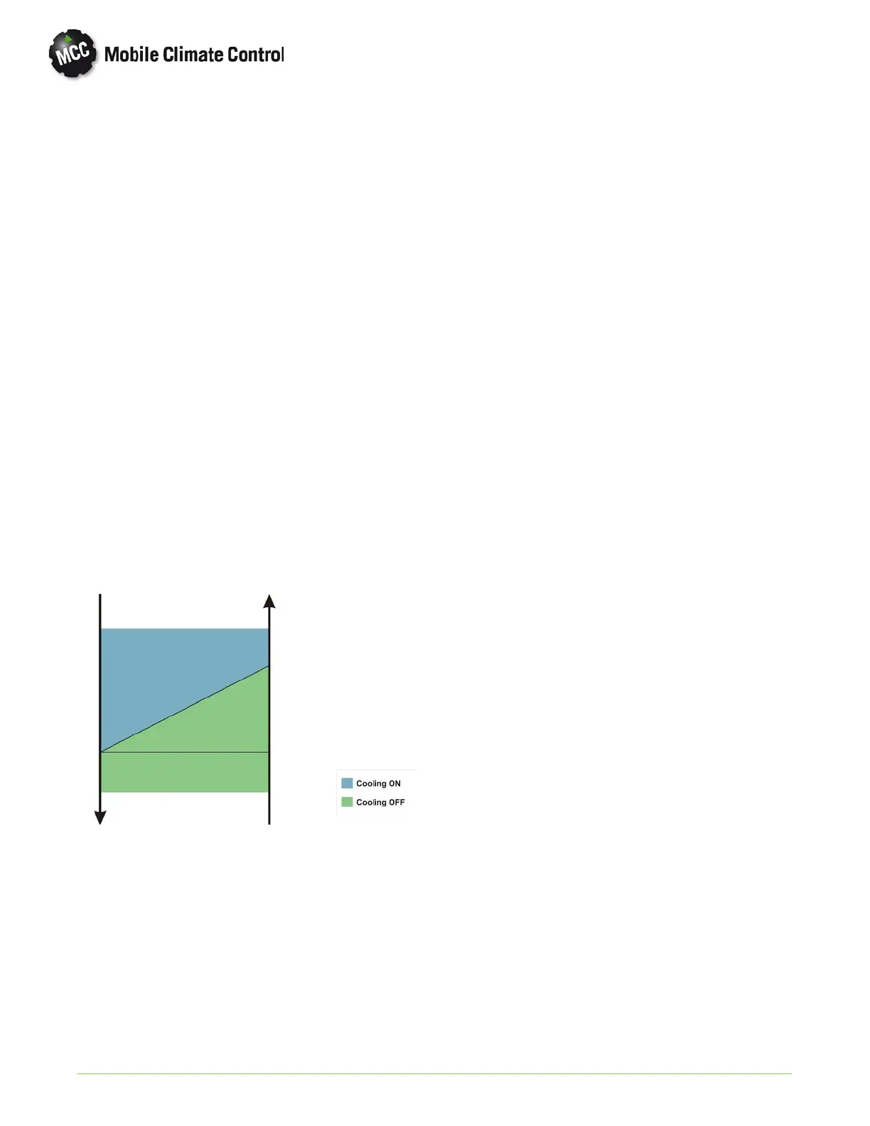
The chart below shows the temperature control of
the compressor operation.
Temperature
Decreasing
Temperature
Increasing
Set Point + 1°F
(0.55°C)
Set Point
The controller will constantly monitor the low and
high pressure switches to pr o tect system
components by monitoring voltage on Pin 13 of
controller from the compressor clutch relay output..
If the freeze u p thermostat, or low pressure switch
circuit opens, the controller will de-energize the
compressor clutch relay, and the condenser fan relay
for a minimum time of 1 minute, or u ntil the open
circuit closes. If the high pressure switch circuit
opens, the controller will de-energize the
compressor clutch relay, and the condenser fan relay
will remain energized to lower system pressure. The
compressor relay will remain open for a minimum
time of 1 minute, or until high pressure switch circuit
closes.
If a low or high pressure condition occurs, an alarm
will be generated and HA shown on the display. If
either condition occu rs 3 times within 30 minutes,
the cooling circuit will be disabled until controller
power is cycled and an alarm LC is shown on the
display. Evaporator fans will remain energized to
provide ventilation.
2.9.4 Heating Mode (If equipped)
The EnviroMATE Controller has the ability to
control output to a heat control valve and boost
pump (OEM supplied), to supply heat provided b y
the engine coolant system. If heat is selected by
pressing the Cool/Heat Key (Item 7 in Figure 2-8),
and the interior temperature is more than 1°Fbelow
set point, the controller willopen a coolant heat valve
to allo w engine coolant flow to the heater coil until
temperature rises to set point.
2.9.5 Sensors
The EnviroMATE Controller constantly monitors
the Return Air (Controller Pins 15 & 11)and
Outside Air sensors (Controller Pins 3 & 7). In the
event the sensor or related wiring causes an Open or
Shorted condition, the controller will default that
particular sensor value to 72°F (22.2°C). An alarm
will be generated and either F1 or F2 will be shown
on the display screen.
2.9.6 Voltage
The EnviroMATE Controller monitors the voltages
being supplied by the OEM by fused circuits on Pins
1&9at the controller. In the event of a low voltage
(below 10 VDC), or an alternator failure, the system
will be disabled, and an alarm bL or AL will be shown
on the display.
2.9.7 Schematics
Typical system schematic for an EnviroMATE single
loop system can be found in Section 5, Figure 5-10.
 Loading...
