2-- 12
© 2012 Mobile Climate Control T-299 Rev. 08/2012
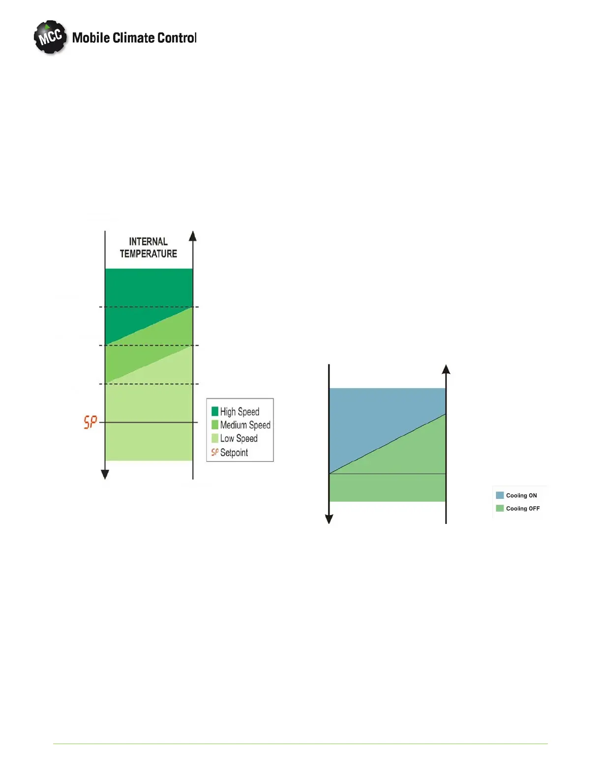
2.10.2 Evaporator Fan Operation (Automatic)
Evaporator fan speeds are controlled automatically
according to the chart shown below. There are 3 fan
speeds controlled by relays mounted to an auxiliary
electrical panel. Each zone will control the
evaporator fan speeds in that zone, according to the
return air temperature sensor controlling that
particular zone.
8_F
4_F
2_F
Temperature
Decreasing
Temperature
Decreasing
Temperature
Increasing
Temperature
Increasing
(4.4°C)
(2.2°C)
(1.1°C)
2.10.3 Evaporator Fan Operation (Manual)
Fan speeds can be controlled manually by pressing
the Vent Key (Item 2 in Figure 2-10), an LED light
will activate in the corner of the Vent Key . After
pressing th e Vent Key, use the Increase/Decrease
Keys (Item 5 and 6 in Figure 2-10) to set t he desired
fan speed. The display will show the following
symbols, indicating selected speed:
u1 = L ow speed
(Controller Output Pin 4 for Zone 1 , Pin 12 for Zone 2)
u2 = Medium speed
(Controller Output Pin 18 for Zone 1, Pin 24 f or Zone 2)
u3 = High speed
(Controller Output Pin 19 for Zone 1, Pin 23 f or Zone 2)
2.10.4 Cooling Mode
When Co o ling Mode is selected (Item 7 in
Figure 2-10), The green LED light will display in
upper left corner of Key by the “Snowflake” symbol.
The controller will then compare the return air
temperature value for each Zone, with the selected
set point temperature. If the value of the return air
temperature for Zone 1 is more than 1°F (0.55°C)
above system set point, the controller will output a
signal on Pin 6 of controller to energize the
condenser and compressor for cooling.
If the value of the return air temperature for Zone 2
is more than 1°F (0.55°C) above system set point, the
controller will output a signal on Pin 10 of controller
to energize the condenser and compressor for
cooling.
Each zone will control the system components for
cooling independently according to need.
The chart below shows the temperature control of
the compressor operation.
Temperature
Decreasing
Temperature
Increasing
Set Point + 1°F
(0.55°C)
Set Point
The controller will constantly monitor the low
pressure switch and freeze up thermostat to protect
system components by monitoring voltage on Pin 14
(Zone 1), and Pin 16 (Zone 2) of controller. If the
freeze up thermostat, or low pressure switch circuit
opens, the controller will de-energize the
compressor clutch relay, and the condenser fan relay
for a minimum time of 1 minute, or u ntil the open
circuit closes.
The controller will constantly monitor the high
pressure switch to protect system components by
monitoring voltage on Pin 13 (Zone 1), and Pin 5
(Zone 2) of controller. If the high pressure switch
circuit opens, the controller will de-energize the
 Loading...
