4-- 15© 2012 Mobile Climate Control T-299 Rev. 08/2012
4.14 EVAPORATOR BLOWER AND/OR MOTOR ASSEMBLY
4.14.1 GEN 4 Series
Replace the blower motor assembly as follows:
a. Disconnect bus battery.
b. Pop-off the snap cap covers and remove all screws
holding the cover to the unit assembly. Remove
the evaporator cover.
c. Remove drain hoses from drain pan assembly.
d. Remove hardware securing drain pan to the
evaporator assembly (4 places).
e. Supporting the blower motor assembly, remove
the hardware that secures the blower motor
assembly to the evaporator. (4 places).
f. Unplug the motor from the evaporator wiring
harness.
g. Replace as necessary.
h. Reinstall blower motor assembly reversing steps a.
thru f.
i. Check blower motor assembly operation.
4.14.2 GEN 5 Series
Replace the blower wheel and/or motor as follows:
a. Disconnect bus battery.
b. Pop-off the snap cap covers and remove all screws
holding the cover to the unit assembly. Remove
the evaporator cover
c. Disconnect the red and black wire from th e
terminal block.
d. Using a 1/8 inch (EM-1 only) or 3/32 inch
(EM-2/3/7) Allen handle loosen the set screw
securing the motor shaft to the blower wheel. The
set screw can be accessed thr o u gh a no t ch ed fin in
the b lower wheel.
e. Remove hardware (4 places) securing the motor
straptothetoppanel.
f. Remove motor strap and motor gasket from
motor assembly.
g. Slide motor assembly shaft out of blower wheel.
h. Pull blower wheel assembly from bearing cup.
i. Replace motor and/or blower wheel if necessary.
j. Carefully place blower wheel assembly into the
bearing cup.
k. Insert motor shaft into the blower wheel hub.
l. Align blower wheel set screw to flat spot on motor
shaft and tighten.
m.Continue to reassemble by reversing steps a. thru
f.
n. Check motor and blower wheel operation.
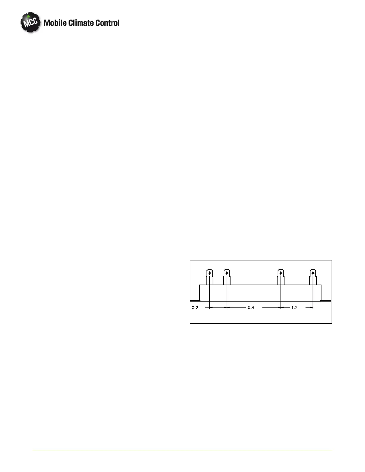
4.15 RESISTORS
4.15.1 GEN 4 Series (Excel)
Low, Medium, High, and High Performance speeds
(for du cted systems) on the GEN 4 series of
evaporators are controlled by the speed selection
switch located on t he drivers control p anel. High
(orange wire) or High Performance ducted (black
wire) speed is determined at time of installation. See
Figure 2-2 for wire connections and Section 5
Electrical for appropriate wiring diagram. Every
GEN 4 series evaporator blower motor assembly has
a speed control resistor. See Figure 4-8 for wire color
connections (speed control) and Ohm's between
prongs.
Total resistance rating of the 4-prong resistor is 1.8
Ohm with a ±5% tolerance rating. Total wattage is
115.
ΩΩ
Ω
Medium
BlackYellow
High High Performance Low
Orange Red
1.8
Ω
Figure 4-8 GEN 4 Series Resistor Assembly
4.15.2 GEN 5 Series
GEN 5 evaporator motor speeds can be controlled
by the driver three ways:
1. Standard GEN 4 type operation usin g the 3 speed
switch and resistors.
2. Variable speed switch control.
3. Electronic Total Control.
Refer to Section 2, GEN 5 Operating Instructions
and Section 5, Electrical, for the appropriate GEN
4/5 wiring diagram.

 Loading...