6
FIG. 2
ASSEMBLY
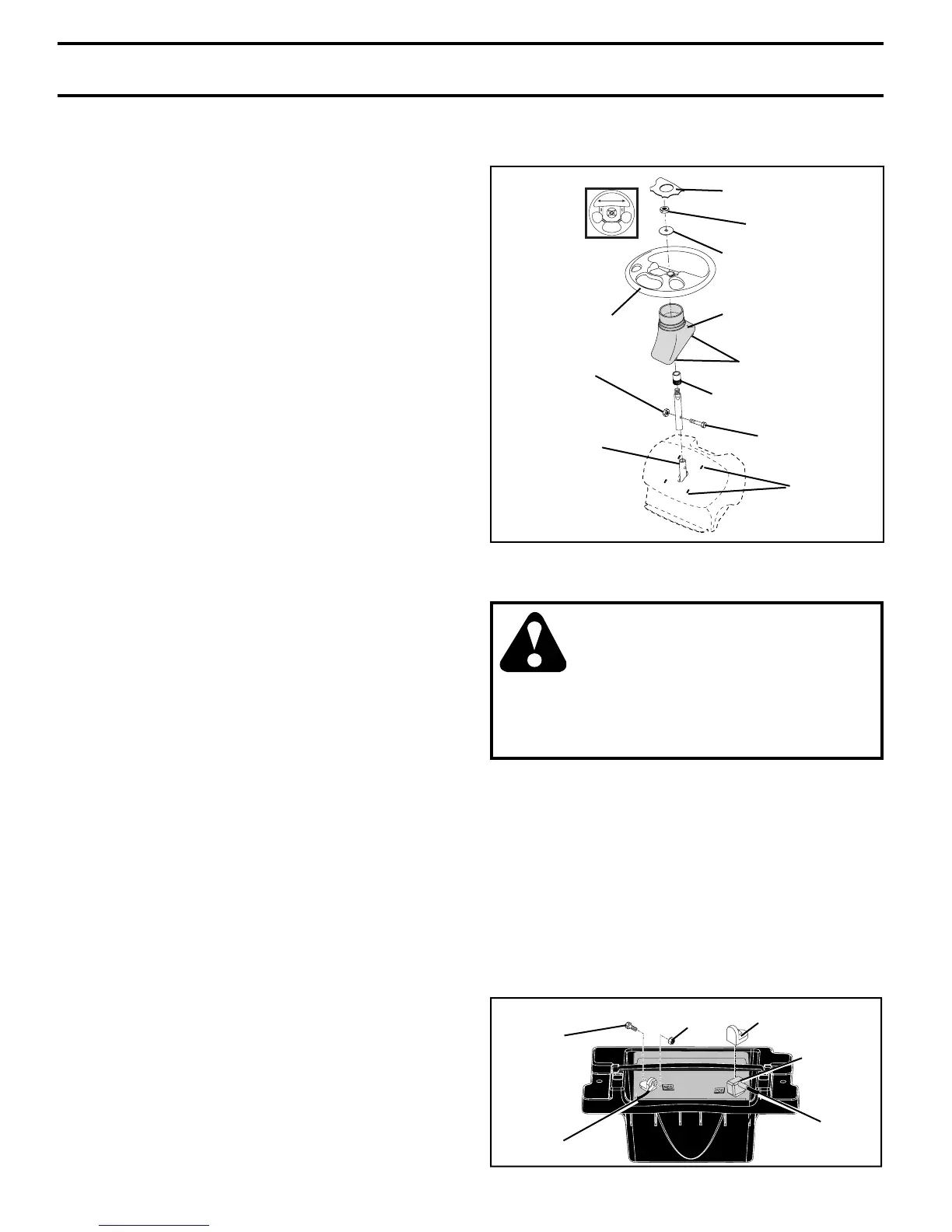
FIG. 1
STEERING WHEEL
INSERT
LOCK NUT
LARGE FLAT WASHER
STEERING WHEEL
STEERING
BOOT
TABS
STEERING
WHEEL ADAPTOR
Your new tractor has been assembled at the factory with exception of those parts left unassembled for shipping pur-
poses. To ensure safe and proper operation of your tractor all parts and hardware you assemble must be tightened
securely. Use the correct tools as necessary to insure proper tightness.
TOOLS REQUIRED FOR ASSEMBLY
A socket wrench set will make assembly easier. Stan dard
wrench sizes are listed.
(2) 9/16" wrenches Utility knife
(1) 1/2" wrench Tire pressure gauge
(1) 3/4" wrench Pliers
(1) 3/4" socket with drive ratchet
(2) 7/16" wrenches
When right or left hand is mentioned in this man ual, it means
when you are in the operating po si tion (seated be hind the
steer ing wheel).
TO REMOVE TRACTOR FROM
CARTON
UNPACK CARTON
• Remove all accessible loose parts and parts cartons
from carton .
• Cut along dotted lines on all four panels of carton.
Remove end panels and lay side panels fl at.
• Remove mower and packing materials.
• Check for any additional loose parts or cartons and
remove.
1/4 LOCKNUT
LOWER
STEERING
SHAFT
1/4 HEX BOLT
TAB
SLOTS
BEFORE REMOVING TRACTOR FROM
SKID
ATTACH STEERING WHEEL (See Fig. 1)
ASSEMBLE EXTENSION SHAFT AND BOOT
• Slide extension shaft onto lower steering shaft. Align
mount ing holes in extension and lower shafts and install
1/4 hex bolt and lock nut. Tighten securely.
IMPORTANT: TIGHTEN BOLT AND NUT SECURELY TO
10-12 FT. LBS TORQUE.
• Place tabs of steering boot over tab slots in dash and
push down to secure.
INSTALL STEERING WHEEL
• Position front wheels of the tractor so they are pointing
straight forward.
• Remove steering wheel adapter from steering wheel
and slide adapter onto steer ing shaft ex ten sion.
• Position steering wheel so cross bars are hor i zon tal
(left to right) and slide inside boot and onto adapt er.
• Assemble large fl at washer, 1/2 hex nut and tighten
se cure ly.
• Snap steering wheel insert into center of steer ing
wheel.
• Remove protective materials from tractor hood and
grill.
IMPORTANT: CHECK FOR AND RE MOVE ANY STA PLES
IN SKID THAT MAY PUNC TURE TIRES WHERE TRACTOR
IS TO ROLL OFF SKID.
CONNECT BATTERY (See Figs. 2)
CAUTION: Do not short battery ter-
minals by allowing a wrench or any
other object to contact both terminals
at the same time. Before connect-
ing battery, remove metal bracelets,
wristwatch bands, rings, etc.
Positive terminal must be connected
fi rst to prevent sparking from acci-
dental ground ing.
• Lift hood to raised position.
• Remove terminal protective caps and discard.
• If this battery is put into service after month and year
indicated on label (label located between terminals)
charge battery for minimum of one hour at 6-10 amps.
(See "BATTERY" in the Maintenance section of this
manual for charg ing in struc tions).
• First connect RED battery cable to positive (+) terminal
with hex bolt and keps nut as shown. Tighten securely.
Slide terminal cover over terminal.
• Connect BLACK grounding cable to negative (-) ter-
minal with remaining hex bolt and keps nut. Tighten
securely.
02745
HEX BOLT
NEGATIVE
(BLACK)
CABLE
POSITIVE
(RED)
CABLE
KEPS NUT
TERMINAL
COVER
DISCARD TER MI NAL
PROTECTIVE CAPS