EasyManua.ls Logo

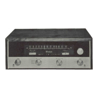
McIntosh MR 71

McIntosh MR 71
15 pages
To Next Page IconTo Next Page
To Previous Page IconTo Previous Page
Loading...
ALIGNMENT
ADJUST
TEST
LIMITS
REMARKS
Top
(Secondary)
and
bottom
(Primary)
cores
of
T1,
T2,
T3,
and
T4
Maximum
possible
negative
voltage
Shunt
to
ground
the
winding
not
being
adjusted
with
a
.01MF
capacitor
in
series
with
a
IK
resistor.
Attenuate
signal
generator
until
output
voltage
at
TP
#1
is
less
than
1.5
volts
with
one
IF
transformer
winding
shunted.
IF
transformers
have
terminal
#1
marked
with
a
green
dot
and
are
numbered
clockwise.
T5
Primary
(Bottom
core)
Same
as
above
'
T5
Secondary
(Top
core)
Adjust
for
0
volts
T6
Primary
(Bottom
core)
Maximum
negative
voltage
If
a
distortion
analyzer
is
available,
omit
this
step
at
this
time.
Adjust
T6
primary
after
step
9.
At
that
time,
use
a
strong
signal
from
FM
generator,
modulate
100%,
and
use
75KC
deviation.
Adjust
primary
for
minimum
distortion.
Should
be
no
greater
than
0.5%.
T6
Secondary
(Top
core)
Adjust
for
0
volts
Oscillator
Trimmer
Maximum
negative
voltage
As
output
increases,
attenuate
signal
generator
to
keep
maximum
output
at
TP
#
1
to
a
low
level.
By
doing
so,
precise
alignment
can
be
achieved.
Oscillator
Coil
SAME
Repeat
steps
6
and
7
until
dial
calibration
is
accurate.
Mixer
trimmer,
RF
trimmer,
and
Antenna
trimmer
SAME
Mixer,
RF,
and
Antenna
coil
Tuning
slugs
SAME
Repeat
steps
8
and
9
until
output
is
as
high
as
possible.
Muting
adj.
control
Turn
muting
switch
to
“in”
position.
Adjust
muting
control
until
background
noise
just
disappears.
IHFM
sensitivity
2.5
microvolt
for
3%
total
noise
and
distortion
Step
11
is
an
overall
sensitivity
check,
and
requires
a
distortion
analyzer
and
FM
signal
generator
with
attenuator.
With
2.5
microvolts
input
at
the
300
ohm
antenna
terminals,
TP
#1
voltage
should
be
3.0
volts
or
more.

Other manuals for McIntosh MR 71

Related product manuals