EasyManua.ls Logo

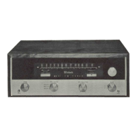
McIntosh MR 71 - McIntosh MR 71 Front Panel Overview; Tuning Dial Scales Description; MR 71 Front Panel Indicators; Front Panel Volume Control

McIntosh MR 71
15 pages
To Next Page IconTo Next Page
To Previous Page IconTo Previous Page
Loading...
DECODER
ALIGNMENT
ADJUST
TEST
LIMITS
On
the
top
of
the
chassis
is
an
opening
labeled
"MPX
Light
Adjust."
Insert
a
screw
driver
into
this
opening
and
turn
the
control
completely
counterclockwise.
1
9KC
phase
coil
Adjust
for
and
19KC
maximum
DC
transformer
(T7)
voltage
Adjust
"MPX
Light
Adjuster”
control
completely
clockwise.
38KC
transformer
bottom
core
38KC
transformer
top
core
Adjust
for
maximum
voltage
Adjust
for
stable
scope
display
1.
Turn
off
19KC
pilot
on
MPX
generator.
2.
Adjust
top
core
of
38KC
transformer
to
obtain
a
stable
and
uniform
1
KC
signal
scope
display.
This
adjustment
may
be
critical,
so
turn
core
very
slowly.
3.
Turn
19KC
pilot
back
on.
1
9KC
phase
coil
30db
separation
Modulate
left
channel
and
measure
right
channel
output.
Adjust
19KC
or
more
phase
coil
for
minimum
right
channel
output
(maximum
separation).
Remove
all
test
leads
from
TP
#2
for
separation
checks.
SAME
Modulate
right
channel
and
measure
left
channel
output.
Separation
in
steps
5
and
6
should
be
at
least
30db.
MPX
light
adj.
control—R3
This
step
checks
the
rejection
of
19KC
and
38KC
frequencies.
Residual
output
should
be
at
least
40db
below
modulated
output.
Turn
control
until
light
comes
on.
Then
back
off
just
enough
to
cause
the
light
to
go
off.
Then
back
off
about
14
of
a
turn
more.
Light
should
operate
ONLY
on
an
MPX
signal.
5

Other manuals for McIntosh MR 71

Related product manuals