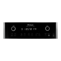
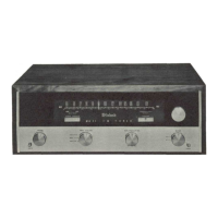
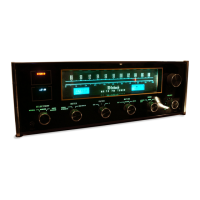
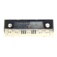
VOLUME
Figure 4. VOLUME Control.
The VOLUME control is the large knob
located to the left side of the dial face. The
volume control adjusts the loudness of both
stereo channels and also the L+R mono-
phonic channel.
INPUT SELECTOR
Figure 5. INPUT SELECTOR.
1. AUX—The AUX position of the INPUT
SELECTOR connects the back panel jacks
marked AUX through the MX110. Use these
jacks to connect any high level program
source through the MX 110. Connections are
made following the instructions on page 11 in
the section titled CONNECTING. Operating
procedure is on page 13 in the section
titled OPERATING INSTRUCTIONS.
2. MPX—The MPX position of the INPUT
SELECTOR connects the multiplex decoder
to the output jacks of the MX110. Listen to
MPX stereo broadcasts in this position. To
properly connect and operate the MX110,
consult the sections titled CONNECTING on
page 11 and OPERATING INSTRUCTIONS
on page 13.
3. FM—The FM position of the INPUT SELEC-
TOR connects FM monophonic programs to
the output jack of the MX110. To properly
operate the MX 110, consult the section
titled OPERATING INSTRUCTIONS on page
13,
4. PHONO 1—The PHONO 1 position of the
INPUT SELECTOR connects the jacks on the
back panel marked PH-1 MAG. and PH-1
XTAL through the MX110. Any stereophonic
or monophonic magnetic phono cartridge
plugged into the PH-1 MAG. jacks is fed
through the MX110. Any constant ampli-
tude cartridge such as a crystal or ceramic
device plugged into the PH-1 XTAL jacks is
fed through the MX110. To properly connect
and operate the MX110 for use with phono
cartridges, see the sections titled CON-
NECTING on page 11 and OPERATING
INSTRUCTIONS on page 13.
5. PHONO 2—The PHONO 2 position of the
INPUT SELECTOR connects the jacks on the
back panel marked PH-2 through the MX110.
Any magnetic phono cartridge plugged into
the PH-2 jacks is fed through the MX110. To
properly connect and operate the MX110 for
use with phono cartridges, see the sections
titled CONNECTING on page 11 and OPER-
ATING INSTRUCTIONS on page 13 .
6. TAPE HD—The TAPE HD position of the
INPUT SELECTOR connects the jacks on the
back panel marked TAPE HEAD through the
MX110. A tape deck that does not contain
its own playback preamplifier is connected to
the MX110 through this position. To properly
connect and operate the MX110 for use with
tape decks, consult the sections titled CON-
NECTING on page 11 and OPERATING IN-
STRUCTIONS on page 13.
MODE SELECTOR
1. L TO L&R—The MODE SELECTOR in the
L TO L&R position connects the left input to
both amplifiers and both loudspeakers.
2. R TO L&R—The MODE SELECTOR in the
R TO L&R position connects the right input to
both amplifiers and both loudspeakers.
3. STEREO REV-The MODE SELECTOR in
the STEREO REV position connects the left
input to the right loudspeaker and right input
to the left loudspeaker.
6
 Loading...