Do you have a question about the MCP CQ5010B and is the answer not in the manual?
Details the sensitivity, trimming ratio, rise time, bandwidth, and input impedance of the vertical system.
Outlines trigger sensitivity, input impedance, max input voltage, and trigger sources/modes.
Specifies sweep time, trimming ratio, sensitivity, and bandwidth for the horizontal system.
Details sensitivity and bandwidth specifications for the X-Y operation mode.
Specifies waveform, range, and frequency for the calibration signal.
Provides display area, accelerating voltage, and display color for the CRT.
Lists voltage range, frequency, and power consumption for the power source.
Details the weight and dimensions of the oscilloscope unit.
Specifies operating temperature, storage environment, and working altitude.
Details the pressure-proof test parameters for the instrument.
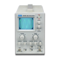
Identifies the location of controls and indicators on the front and rear panels.
Explains the function of each control switch and connector on the oscilloscope.
Ensures the correct voltage is used to prevent damage and accidents.
Guides through powering on, warm-up, and initial display adjustments.
Details how to adjust VOLTS/DIV and VAR for waveform display.
Explains the selection of INT, EXT, and LINE trigger sources.
Covers sweep setup, position adjustment, and trigger type selection.
Provides information on probe operation, impedance, and adjustment.
Details pre-measurement checks, trace rotation, and probe compensation adjustments.
Step-by-step guide for measuring peak-to-peak voltage using the oscilloscope.
Procedure for measuring DC voltage levels relative to a zero reference.
Methods for measuring time intervals, period, frequency, rise, and fall times.
Instructions for measuring TV signals using the oscilloscope's trigger modes.
Details on using the oscilloscope for X-Y mode operations and applications.
| Brand | MCP |
|---|---|
| Model | CQ5010B |
| Category | Test Equipment |
| Language | English |