C
Connor ValenzuelaAug 16, 2025
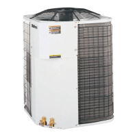
What to do if the McQuay ACZ 010A Heat Pump compressor will not run?
- MMario JohnsonAug 16, 2025
If the McQuay Heat Pump compressor will not run, first ensure the main switch is closed. Check for blown fuses or open breakers, inspecting electrical circuits and motor windings for shorts, overloads, and loose connections; replace the fuse or reset the breaker if necessary. Also, check if thermal overloads have tripped (they auto reset). Inspect the contactor or coil for defects and repair or replace if needed. Determine if a protection device has shut the system off and correct the cause. If no cooling is required, the compressor should start on a call for cooling. Check if the liquid line solenoid will not open and repair or replace the coil if needed. Inspect the motor for open or short circuits, or burnout. Finally, check all wire junctions and tighten all terminals.