1-8
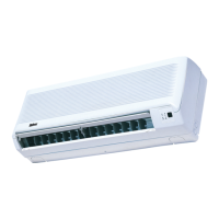
IR signal receiver
When an infrared remote control operating signal has
been transmitted, the signal receiver on the indoor unit
will make a <beep> sound to confirm acceptance of the
signal transmission.
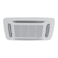
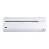
Cooling unit / Heat Pump unit
The table shows the LED indicator lights for the air condi-
tioner unit under normal operation and fault conditions.
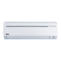
The LED indicator lights are located at the middle of the air
conditioner unit.
The heat pump units are equipped with an “auto” mode
sensor whereby it will provide reasonable room temperature
by switching automatically to either “cool” or “heat”
mode according to the temperature set by the user.
INDICATOR LIGHTS
LED indicator lights
IR Receiver
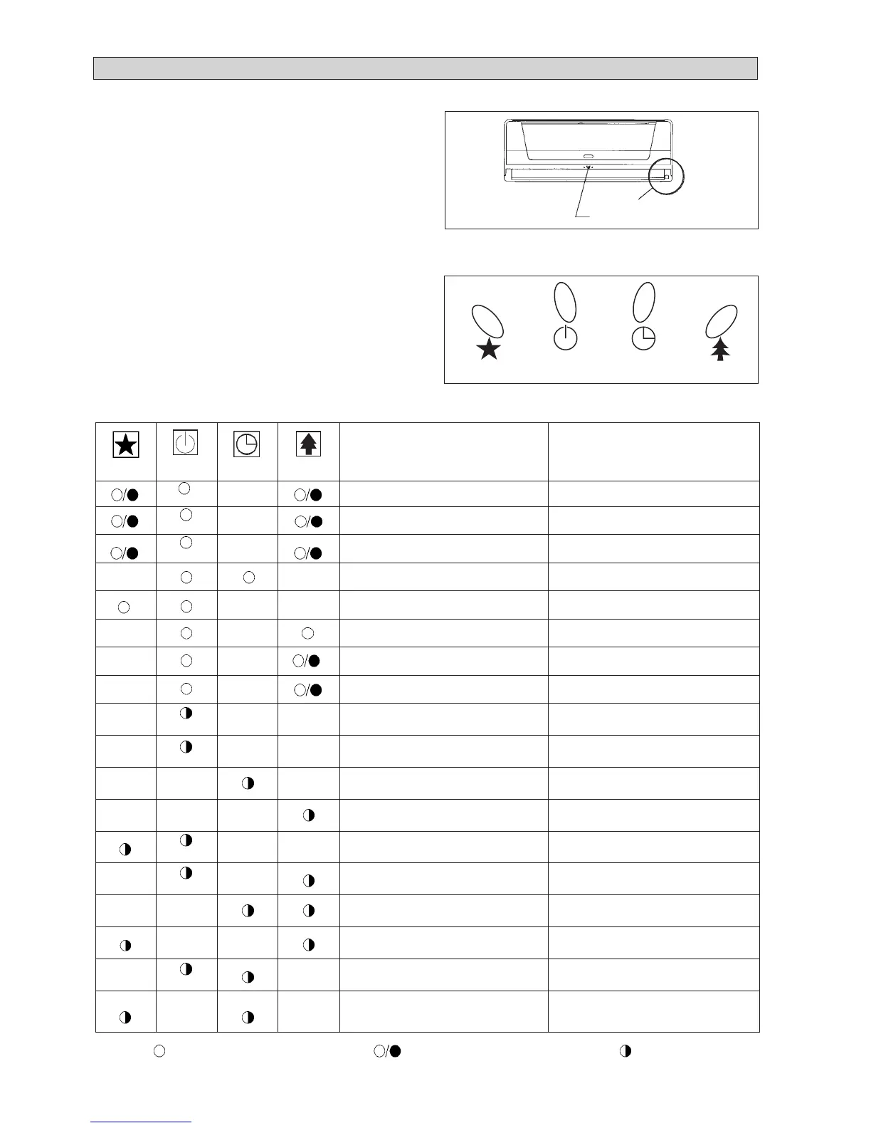
LED Indicator Lights for Cooling Unit / Heat Pump
Unit
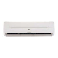
Sleep Mode Cool Timer Ionizer/NTP
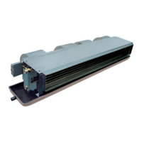
Inverter Unit (MWMX-G)
LED Indicator Lights : Normal Operation And Fault Conditions For Cooling / Heat Pump Unit
Normal Operation / Fault Indication Action
Cool mode –
Heat mode –
Auto mode in Cooling/Heating operation –
Timer on –
Sleep mode on –
Ionizer on –
Fan mode on –
Dry mode on –
Defrost operation –
Indoor temperature sensor loose / short Call your dealer
Coil temperature sensor loose / short Call your dealer
Outdoor temperature sensor loose / short Call your dealer
Compressor overload protection Call your dealer
IPM / PFC error Call your dealer
Outdoor total current trip / DC peak Call your dealer
Compressor overheat / Gas leak Call your dealer
Indoor fan feedback error Call your dealer
Communication error between indoor
and outdoor
Call your dealer
COOL/HEAT
(GREEN/RED)
Orange
Red
Green
ON
ON or OFF Blinking
Red
Green
Green
Green
Green

 Loading...