CONTROL CENTER
All electrical controls are enclosed in a control center with
locking, hinged access door(s). A partition separates the ad-
justable safety controls from the starting and operating
con-
trots. A “deadfront” panel covers all starting and operating
controls so that no electrical contacts or terminals are
ex-
posed. The deadfront panel is hinged for servicing. The
ad-
justable controls are covered and can be adjusted without fear
of contacting line voltage.
Please refer to
IM
493 for control section layout, all low
voltage field wiring and normal sequence of operation for units
equipped with
MicroTech
control.
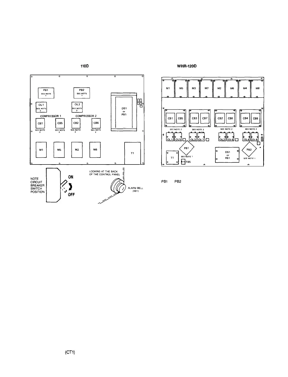
POWER PANEL LAYOUT
Figure 27. WHR-040D thru
1lOD
Right Side, High Voltage Control Section
1
pq”
&,
0 0
Figure 28. WHR12OD thru 240D
Right Side, High Voltage Power Section
NOTES:
1. PBl and
Pf32
are used with multiple point power wiring.
2.
Circuit breakers and overloads are provided as an option. The power panel
could contain one, both, or neither of these options.
WIRING
FIELD WIRING, POWER
The WHR
“D”
vintage chillers are built standard with com-
pressor contactors and power terminal block, designed for
single power supply to unit. Optional power connections in-
clude a nonfused disconnect switch mounted in the control
box or multi-point power connection.
A factory installed control circuit transformer is available
as an option with single power supply or disconnect switch;
it is not available with multi-point option.
On water cooled units only, optional compressor overloads
are available, allowing reduced unit ampacity ratings and
smaller field wiring.
tional Electrical Code and/or local requirements.
An open fuse indicates a short, ground, or overload. Before
replacing a fuse or restarting a compressor or fan motor, the
trouble must be found and corrected. Tables in the Electrical
Data section give specific information on recommended wire
sizes.
Unit power inlet wiring must enter the top of the control box
(right side) through a patch plate provided for field terminating
conduit. (Refer to control panel layout drawings for general
location of power inlet and components.)
Optional circuit breakers are available for backup com-
WARNING: Use only copper conductors in main terminal
pressor short circuit protection on 040D thru
110D
units and
block. If the power input conductors are aluminum, use a com-
are standard on all four (4) compressor units 120D thru 240D.
pression splice to change to copper before terminating in
Wiring and conduit selections must comply with the Na-
block.
TYPICAL CONTROL AND SAFETY WIRING DIAGRAMS
Refer to IM 493 for typical control and safety wiring or actual unit wiring diagrams.
CURRENT TRANSFORMER
The typical power wiring diagrams shown on pages 19 thru 35 include the current transformer
(CTI)
wiring shown in Figure 29. CT1 provides a O-4 vdc signal to the
MicroTech
panel which
is then converted to XXX% RLA.
IM 508 I Page 29
 Loading...