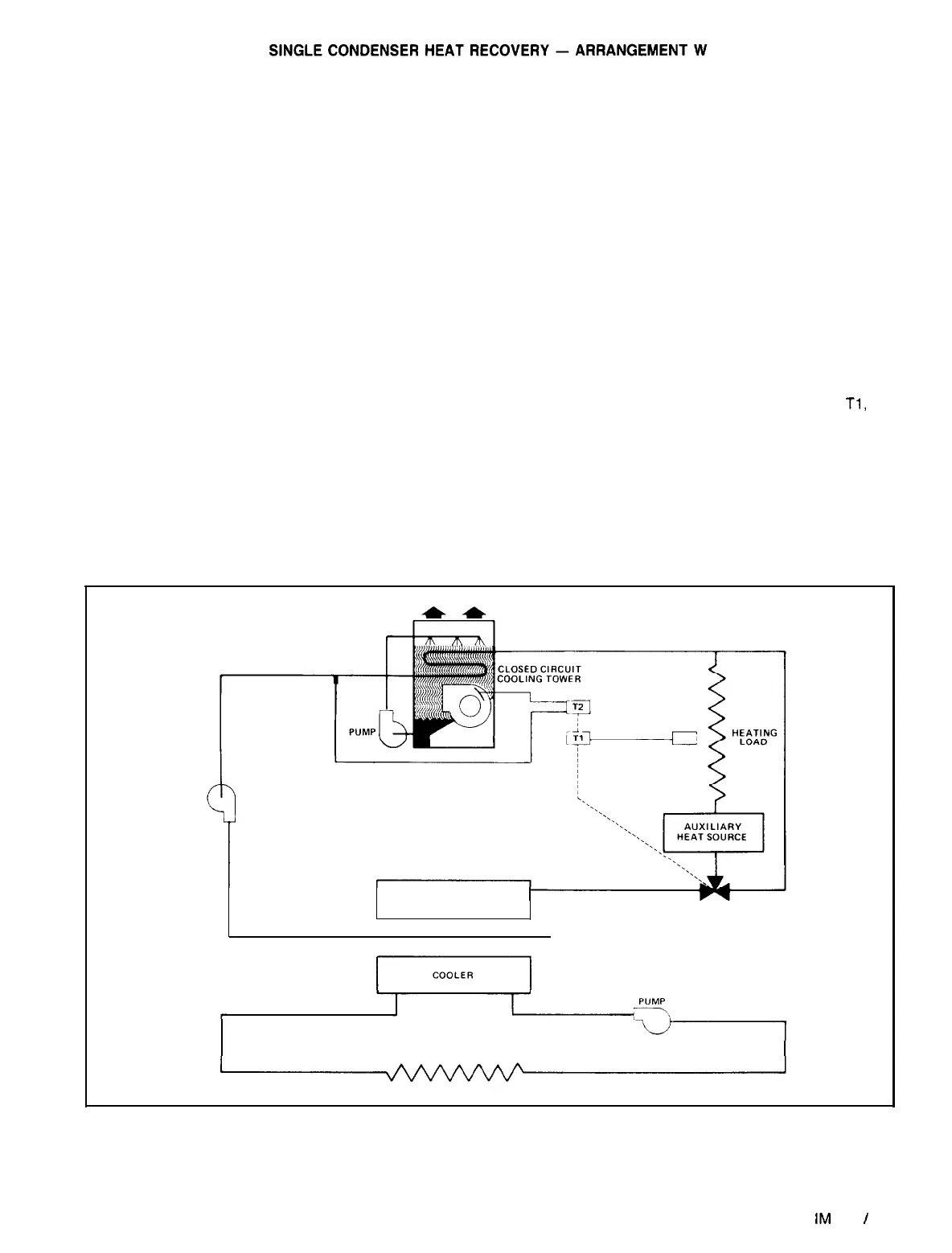
Single circuit heat recovery employs a standard water
cooled chiller equipped with heavier electrical components
and a 380 psig high pressure limit switch. These modifica-
tions allow leaving condenser water temperatures up to 135°F
for building or process heating applications.
A typical heat recovery arrangement will include a closed
circuit cooling tower used to reject unwanted condenser heat
to the outdoor ambient air. The cooling tower should be
sized to reject all the condenser heat during summer design
operation. This insures proper operation in the
nonheat-
recovery mode. Use of a closed circuit tower is normally re-
quired in order to prevent fouling of heating coils in the heat
recovery loop. Condenser water remains free of contamina-
tion from minerals and impurities normally contained in make-
up water in an open cooling tower.
If a closed circuit cooling tower is to be located in an am-
bient temperature below freezing, protection against coil and
sump freeze-up must be provided. Coil freeze protection can
be provided by using a glycol solution or by maintaining a
heat load on the coil
at all times and maintaining water flow
through the coil. Sump water freeze protection can be pro-
vided by locating the spray water circulating pump and sump
tank inside a heated space or by placing heating coils in the
sump. Head pressure and water temperature are normally
controlled by the tower capacity control. Adequate capacity
control is usually obtained by fan cycling and regulating
dampers located in the fan discharge. This will maintain a
constant tower water temperature. Consult the closed circuit
manufacturer for information on specific applications.
An auxiliary heat
source is necessary if the available con-
denser heat is not sufficient to satisfy all of the heat load.
The auxiliary heat source must be located between the con-
denser and the heat load and the control should be inter-
locked with the closed circuit tower to prevent auxiliary
heating while rejecting heat to the ambient.
When the heating load is satisfied, a two-position, three-
way valve is set to divert condenser water around the heat
load and the auxiliary heat source. Whether operating in sum-
mer or winter, the chiller is always controlled by the cooling
load and not the heating load.
TYPICAL OPERATION
-
On a call for cooling, the chiller
starts and hot condenser water flows through the diverting
valve to the closed circuit cooling tower rejecting heat to the
outdoors. The tower dampers modulate to maintain a pro-
per entering condenser water temperature which will give ef-
ficient operation by means of the proportional controller T2
located in the outlet fluid line of the tower.
When a heating load is sensed by mode switch
Tl,
the
three-way valve is switched to allow condenser water to flow
through the heating circuit. The proportional controller T2 is
also reset upwards to give the desired water temperature for
heat recovery. The unused condenser heat will be rejected
out through the closed circuit tower. If the condenser heat
of rejection cannot satisfy the heating load after an ap-
propriate delay, the auxiliary heat source will be activated.
Figure
11. Typical Single Condenser (Per Refrigerant Circuit) Heat Recovery
PUMP
HEATRECOVERY
CONDENSER
TWO POSITION
DIVERTING VALVE
COOLING LOAD
NOTE: The schematic shows one refrigerant circuit. Models with two refrigerant circuits have two condensers
IM
508
I
Page 11
 Loading...