IM-447 / Page 15
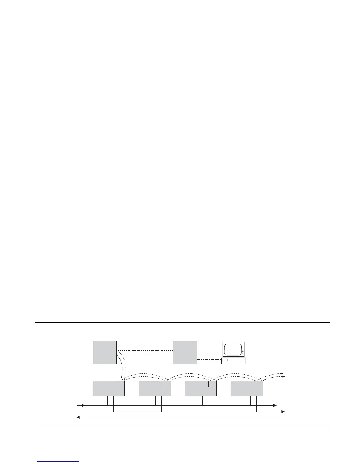
MicroTech Network Control System
Each Console Heat Pump Unit is available with a MicroTech
Unit Controller. The unit controller is a factory mounted,
preprogrammed and pre-tested stand-alone microprocessor
capable of communicating to a local personal computer
through the MicroTech Network Master Panel.
The MicroTech control system includes unit-mounted
return air; discharge air and leaving water temperature
sensors; tenant setpoint adjustment knob and an optional
tenant override button; and the capability of replacing the
return air sensor with a wall-mounted room sensor.
The MicroTech Network Control System is a fully
distributed, direct digital control (DDC) system which allows
the owner to control and monitor water source heat pump
units and auxiliary equipment through a personal computer
to maintain comfort conditions.
The PC has the ability to communicate with each heat
pump unit and with the entire system through two dedicated
conductors, twisted and shielded, in a “daisy chained”
format. Each controller utilizes EEPROM microprocessor
technology, retaining programmable setpoint parameters and
control logic. Each controller may operate as stand-alone,
independent of the network communications and will:
• Control heating and cooling from a return air sensor.
• Provide fan and compressor operation.
• Monitor all safety controls.
• Monitor discharge air temperature.
• Monitor leaving water temperature.
• Provide status of all vital unit functions.
• Provide optional control output.
The MS-DOS compatible software package allows the
operator to interface with each unit controller into the entire
network. Parameters within each controller are factory set
but can be changed from the PC. All control sequencing,
stop/start and safety monitoring is displayed on the PC
screen with the following unique values and parameters for
each unit:
• Return air, discharge air and entering water temperatures.
• Compressor, fan and reversing valve status.
• High pressure, low temperature, brownout and drain pan status.
• Occupied and unoccupied heat and cool setpoints.
• Auto/manual and occupied/unoccupied fan control.
• Mode, fault, system, schedule and setpoint operation.
• Compressor starts and fan run hours.
• Load shed level and tenant override.
In addition, the following unique operation and
maintenance parameters can be displayed for each unit:
• Leaving water temperature
• Return air temperature setpoint adjustment
• Adaptive optimal start
• Occupied/unoccupied (on/cycle) fan mode
• Room temperature warning
• Filter changes from fan hours
• Compressor management: On/off differential, maximum
off time, maximum cycle
Time schedules can be graphically displayed showing start/
stop times for each day of the week and holidays. Up to 16
holiday dates and duration cycles can be set for a total of
240 possible holiday dates. Each heat pump can be assigned
to a different time schedule and any number of heat pumps
can be assigned to the same time schedule.
Group summary screens are available to display various
parameters for 12 units. Screens are grouped to cover major
groups such as temperatures, setpoints and status.
Control and monitoring of the entire water source heat
pump system through the MicroTech Network includes the
MicroTech Loop Water Controller and Application Specific
Controllers complete with graphic displays.
Wall-mounted room sensors are available to control the
heating and cooling operation of each MicroTech Unit
Controller. These include a basic room sensor with optimal
override, LED status and tenant setpoint adjustment.
For remote access, a Modem Access Unit allows a remote
PC to call the MicroTech Network through phone lines as
well as allowing the MicroTech Network to dial predefined
phone numbers.
Personal
Computer
Heat Pump
MicroTech
Network Master Panel
MicroTech
Loop Water Controller
Heat Pump Heat Pump Heat Pump
Communications To
Additional Units
Supply
Return
Network graphic
 Loading...