EasyManua.ls Logo

McQuay WMA series - User Manual

McQuay WMA series
20 pages
Print Icon
To Next Page IconTo Next Page
Loading...
Installation & Maintenance Data IM 447-9
Group: WSHP
Part Number: 107225603
Date: June 2006
Installation & Maintenance Data
Console Water Source Heat Pump
Models WDA, WDB, WDD, WDE, WDF, WDG, WDH, WDS, WLA, WLB, WLC, WLL
WMA, WMB, WMC, WMD, WME, WMF, WMG, WMH, WMU, WMK, WML
Model Nomenclature . . . . . . . . . . . . . . . . . . . . . . . . . . . . . 2
Checking for Damage . . . . . . . . . . . . . . . . . . . . . . . . . . . . 3
Installation . . . . . . . . . . . . . . . . . . . . . . . . . . . . . . . . . . . . 3,4
Electrical Connections . . . . . . . . . . . . . . . . . . . . . . . . . . . 5
Cabinet Power Connections . . . . . . . . . . . . . . . . . . . . . . . 5
Water Connections . . . . . . . . . . . . . . . . . . . . . . . . . . . . . . 6
Piping . . . . . . . . . . . . . . . . . . . . . . . . . . . . . . . . . . . . . . . . 7
Cleaning & Flushing System . . . . . . . . . . . . . . . . . . . . . . . 7
Operating Limits . . . . . . . . . . . . . . . . . . . . . . . . . . . . . . . . 8
Electrical Data . . . . . . . . . . . . . . . . . . . . . . . . . . . . . . . . . . 8
Unit Operation . . . . . . . . . . . . . . . . . . . . . . . . . . . . . . . . . . 8
Wiring Diagrams Mark IV/AC-Units . . . . . . . . . . . . . . 9,10
Control Options . . . . . . . . . . . . . . . . . . . . . . . . . . . . . . . . 11
Thermostats Mark IV/AC-Units . . . . . . . . . . . . . . . . . . 12
Pump Restart Relay . . . . . . . . . . . . . . . . . . . . . . . . . . . . 13
MicroTech Control Units . . . . . . . . . . . . . . . . . . . . . . . 14,15
Field Installed Options . . . . . . . . . . . . . . . . . . . . . . . . . . 16
Optional Outside Air Damper . . . . . . . . . . . . . . . . . . . . . 18
Troubleshooting . . . . . . . . . . . . . . . . . . . . . . . . . . . . . . 18,19
Maintenance . . . . . . . . . . . . . . . . . . . . . . . . . . . . . . . . . . 19
Contents
©2006 McQuay International
®
Question and Answer IconNeed help?

Do you have a question about the McQuay WMA series and is the answer not in the manual?

Summary

Console Water Source Heat Pump

Model Nomenclature

Checking for Damage

Installation

Electrical Connections

Water Connections

Piping

Cleaning and Flushing System

Operating Limits

Electrical Data

Unit Operation

Typical Wiring Diagrams

Control Options

Thermostat Connection Diagrams

MicroTech Network Control System

Troubleshooting

Neither fan nor compressor runs

Troubleshooting steps for when the fan or compressor fails to start, checking fuses, wiring, and controls.

Fan operates but compressor does not

Steps to diagnose why the fan runs but the compressor does not, checking capacitor, wiring, and high pressure.

Maintenance

Overview

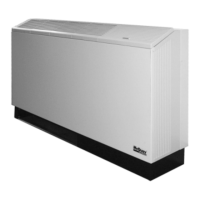
The document describes the McQuay Console Water Source Heat Pump, a type of air conditioning unit designed for indoor installation. This manual, identified as IM 447-9 and dated June 2006, covers various models including WDA, WDB, WDD, WDE, WDF, WDG, WDH, WDS, WLA, WLB, WLC, WLL, WMA, WMB, WMC, WMD, WME, WMF, WMG, WMH, WMU, WMK, and WML.

Function Description:

The Console Water Source Heat Pump is designed to provide heating and cooling in a controlled indoor environment. It operates by transferring heat to or from a water loop, making it an efficient solution for various building types. The units are available with different nominal capacities ranging from 7,000 to 19,000 BTUs. They can be configured for various voltages, including 115-60-1, 208/230-60-1, 265-60-1, and 230-50-1.

Important Technical Specifications:

  • Dimensions: The total unit depth is 10.75 inches (273mm). Specific dimensions for standard and height units (sizes 007-012 and 015-019) are provided in both inches and millimeters for the cabinet backwrap and subbase.
  • Operating Limits:
    • Air Limits:
      • Minimum Entering Air (db/wb): 65°F (18°C) for cooling, 55°F (14°C) for heating.
      • Normal Entering Air (db/wb): 80/67°F (27/19°C) for cooling, 70°F (21°C) for heating.
      • Maximum Entering Air (db/wb): 90°F (32°C) for cooling, 80°F (27°C) for heating.
    • Water Enthalpy:
      • Minimum Entering Water: 60°F (16°C) for cooling, 55°F (14°C) for heating.
      • Normal Entering Water: 85°F (29°C) for cooling, 70°F (21°C) for heating.
      • Maximum Entering Water: 110°F (43°C) for cooling, 90°F (32°C) for heating.
    • Electrical Data: Operating voltages are specified with minimum and maximum ranges for 115/60/1, 208-230/60/1, 265/60/1, and 230/50/1 units. All 208-230V single-phase units are factory wired for 208V operation unless otherwise specified.
  • Control System: Units can feature either Mark IV/AC controls or MicroTech Network Control System.
    • Mark IV/AC Controls: These units incorporate a printed circuit board, providing 24 VAC output for low voltage terminals. Features include continuous fan operation, auto cooling/heating, lockout circuits for abnormal conditions (high pressure, low temperature, condensate overflow, brownout protection), remote reset of automatic lockouts, fault retry to minimize nuisance trips, random start, compressor time delay, night setback, load shed, shutdown, defrost cycle, and LED/fault outputs.
    • MicroTech Network Control System: This is a fully distributed, direct digital control (DDC) system with a unit controller (factory mounted, preprogrammed, pre-tested microprocessor) capable of communicating with a local personal computer via a Network Master Panel. It includes return air, discharge air, and leaving water temperature sensors, with options for a wall-mounted room sensor. The system allows control and monitoring of water source heat pump units and auxiliary equipment, offering features like:
      • Control of heating and cooling from a return air sensor.
      • Fan and compressor operation.
      • Monitoring of safety controls, discharge air temperature, leaving water temperature, and vital unit functions.
      • Programmable setpoint parameters and control logic retained in EEPROM microprocessor.
      • Graphical display of time schedules, holiday dates, and duration cycles.
      • Group summary screens for multiple units.
      • Remote access via Modem Access Unit.
  • Piping: Units are designed for two-pipe reverse return configuration, which is inherently self-balancing. Recommended water temperature differential for proper flow in cooling mode is 10°F to 14°F (-5°C to -8°C). Piping can be steel, copper, or PVC, adhering to local codes. Flexible hoses are recommended for sound attenuation.
  • Condensate: Each unit includes a 3/4" (19mm) I.D. clear vinyl condensate hose, internally trapped within the chassis, extending 14" (356mm) for connection to field condensate piping.

Usage Features:

  • Installation: Units must be installed indoors, against a wall, and level. Proper sealing of electrical wiring/conduit and wall cavities is crucial to prevent condensation, water leakage, and cold air infiltration. Flexible piping and electrical wiring are recommended to prevent vibration transmission.
  • Control Options:
    • Thermostats: Compatible with 7-Day Programmable Electronic Thermostats (P/N 107095901) and Non-Programmable Electronic Thermostats (P/N 668054201). Optional remote sensors (P/N 667720401) can be used, requiring specific wiring and disabling of the main sensor on the thermostat.
    • Pump Restart Relay Kit (P/N 061419001): This option allows the WSHP to signal the loop water controller (LWC) panel to restart the loop pump when compressor operation is required. It can be daisy-chained for up to 200 Mark IV/AC boards.
    • Multiple Unit Control Panel: Available for controlling up to 3 units (P/N 056794201) or up to 2 units (P/N 106059801) from a single thermostat. These boards use VAC or VDC relays, respectively, and provide protection from electrical damage.
    • Motorized Valve & Relay (for 007-019 units): Allows the valve to open on a call for compressor operation, stopping or diverting water flow when not needed.
    • Auxiliary Relay (P/N 106059701): Interfaces external equipment with the Mark IV/AC board, providing fault signals, unit operation signals, or remote control capabilities.
    • MicroTech 2000 Field Installed Options: Provides up to 4 configurable outputs for scheduled output, auxiliary heat (skin heat), fresh air damper control, or motorized water valve control. An Auxiliary Module Kit (107239001) may be needed for additional outputs.
  • Optional Outside Air Damper: Allows for the introduction of outside air. Caution is advised for cold weather operation, as it can lead to erratic unit performance. Proper sealing during installation is critical.

Maintenance Features:

  • Filter Changes: Filters should be checked at 60-day intervals initially, with frequency adjusted based on environmental conditions (e.g., lint from carpeting in motels). Filters should be changed if light cannot be seen through them.
  • Condensate Drain Pan: Should be checked, cleaned, and flushed annually. The Mark IV/AC equipment includes a condensate overflow control device, which can lock out compressor operation if the pan is full.
  • Performance Measurement: Recording volt-amps and water temperature differences (heating and cooling) is recommended for tracking equipment condition over time.
  • Troubleshooting: The manual provides guidance for common issues such as:
    • Compressor attempts to start but doesn't (check capacitor, compressor winding, run capacitor).
    • Compressor short cycling (check thermostat, relays, run capacitor, high/low pressure switches, reversing valve).
    • Insufficient cooling or heating (check thermostat, airflow, reversing valve, capillary tubes, water flow).
    • Insufficient water flow through condenser (check valves, air in lines, circulating pump).
    • Water drips from conditioner (check plugged condensate drain, dirty filter, blower motor speed, mispositioned blower, drain traps).
    • Noisy unit operation (check fan wheel, compressor isolator mounts, tubing contact, panel screws, contactor relays, water balance).
    • Neither fan nor compressor runs (check fuse/circuit breaker, wiring, supply voltage, control system/thermostat/transformer).
    • Fan operates but compressor does not (check capacitor, wiring, high/low pressure trips, thermostat setting, compressor overload, compressor winding).
  • Water Treatment: It is critical to ensure proper water treatment to prevent problems related to flow and premature component failure. Trisodium phosphate is no longer recommended for flushing; instead, longer flushing with 80°F (27°C) water is advised. The system should be refilled with clean, slightly alkaline water (pH 7.5 to 8.5), and commercial-grade HVAC antifreeze may be added if needed.

McQuay WMA series Specifications

General IconGeneral
BrandMcQuay
ModelWMA series
CategoryHeat Pump
LanguageEnglish

Related product manuals