IM-447 / Page 9
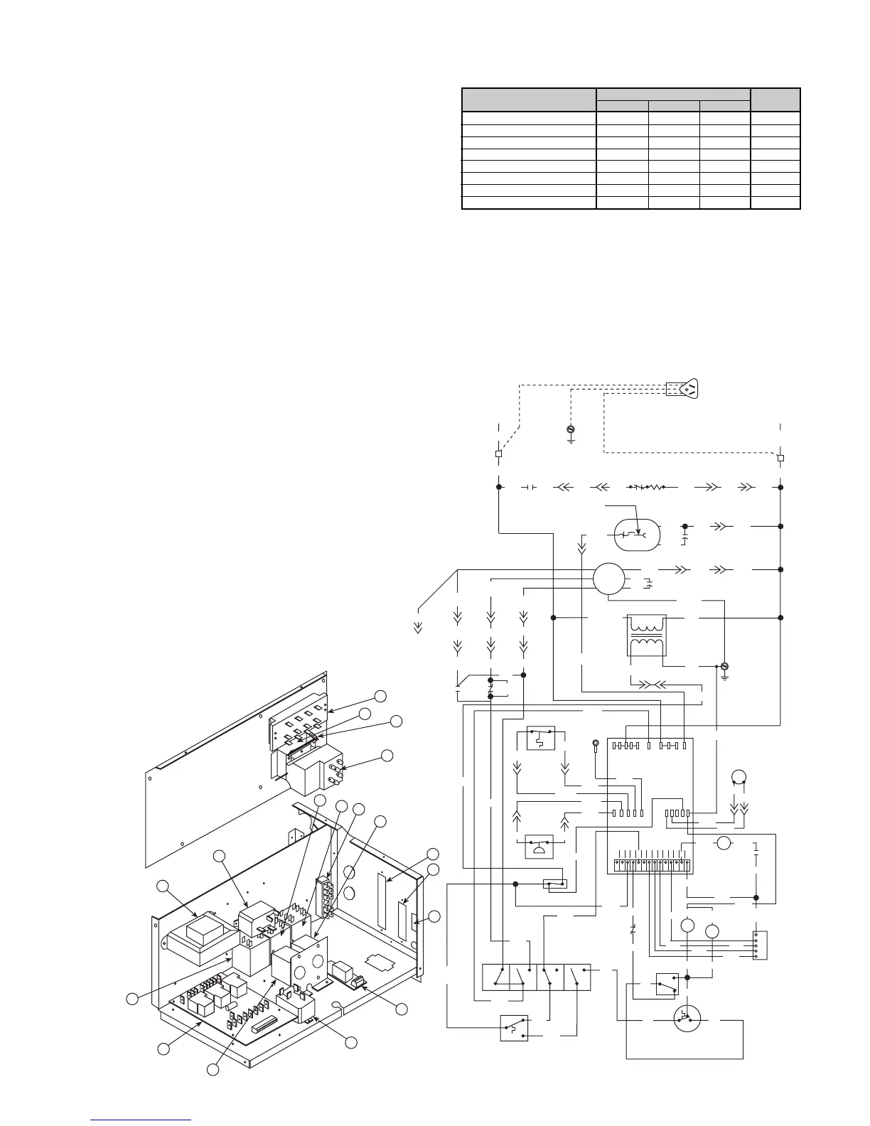
Typical Wiring Diagrams for
Units with Mark IV/AC Controls
Notes
1. Terminal block on PC board
provides 24 VAC at terminals
C and R. All other terminals are
24 VDC output.
2. All temperature and pressure
switches are normally closed.
3. Component layout is typical,
some components shown may
not be used.
4. Field supplied relays installed
on the unit terminals W1, W2,
Y1, Y2 and G may introduce
electrical noise. Never install
relay coils in series with the
inputs.
10
55
9
3
2
1
16
13
12
18
14
15
17
6
4
11
7
8
Fan
Motor
Optional Cordset
L1
L2
Ribbed Lead
Common
Compressor
Capacitor
Capacitor
Transformer
R
S
BK
OR13
TB
TB
OR2
Terminal Board 2
MCO
4-Button
Switch
H
L1
RD
HI
BK RD
L2 L3
LO
W
2
1
3
MCO Thermostat
OR1
BL1
OR
11
C
RD8
BL2
Stop/Start Switch
HI Press
BR
BR
HP HP LT LT COF
BR1
WH2
BK3
OR12
OR4
S
RV RV V C
C
o
m
p
L1
Common
Fan
Mark IV
PC Board
RD3
BK3
LO Temp
BK2
OR4
WH3
Condensate
Sensor
BK5
BK4
RD1
BK1
RD1
RD (007, 012, 015)
OR (019) BL(009)
WH 115V
RD 208V
OR 230V
BR 265V
BK
YE
GN/YE
24VAC
BR
BR
WH
BR2 BR2
WH1
WH2
WH3
BR1 BR3
BL
BK10
(Not used on all sizes)
RD 208/230V
WH 115/265V
(Heat Pump Only)
Reversing
Valve Solenoid
GN/YE
BK12
R
BK11
Limit
Switch
Heater
BL3 BL2 BL1OR3OR2OR1RD4
HR
RD8
BL (007, 015)
BK (009, 012, 019)
BK1
BFR
BL7
(007, 015)
BL
(012, 019)
BL6
(009, 012, 019)
BL7
(009, 012, 019)
BK2
W
2
OG
W
1
FELUAPV C
R
C
P
U
L
E
BR
BFR
2
1
3
Boilerless
Thermostat
Standby Electric
Heat Switch
BK
RD
BL11WH5
WH9
GY9
BL9
GR9
HR
BR
BL5
OR9
BR4
BR
OR14
WH4
BR4
OR9
Y
1
BR5
OR15
WH1
OR9
BL9
RD (009)
Splice Connector
BL70
BL70
BL70
BR
BR
BL10
BL10
RD9
(009)
BL5
Component Layout
1. Tap-Touch Switch
2. Thermostat
3. Terminal Block
4. PC Board
5. Transformer
6. Boilerless Relay
7. Shutdown Relay
8. Auxiliary Relay
9. Heater Relay
10. Water Reg Valve Relay
11. Low Limit Thermostat
12. Night Setback Thermostat
13. Override Switch
14. Terminal Board 1
15. Terminal Board 2
16. Stop/Start Switch
17. Standby Electric Heat Switch
18. Boilerless Fan Relay
>> Plug Connection
TB Terminal Block
ACO Automatic Change Over
MCO Manual Change Over
BR Boilerless Relay
HR Heater Relay
60 Hertz Mark IV MCO Boilerless Constant Fan
Figure 7.
Indication
LED’s
Fault
Yellow Green Red Output
Normal Mode Off On Off Off
High Pressure Fault Off Off Flash On
Low Temperature Fault* Flash Off Off On
Condensate Overflow On Dim Off On
Brown-out Off Flash Off On
Load Shed Off Off On Off
Unoccupied Mode On On Off Off
Unit Shutdown Off Flash Off On
Note: It will require removal of the front panel and control box cover in order
to view the PC board.
*In heating mode only.
heat exchanger. After 60 seconds, the compressor is locked
out. If the condensate sensor detects a filled drain pan, the
compressor operation will be suspended only in the cooling
mode. The unit is reset by opening and closing the disconnect
switch on the main power supply to the unit in the event the
unit compressor operation has been suspended due to low
temperature (freezestat) switch, or high pressure switch.
The Mark IV/AC control circuit has a fault output signal to
an LED on a wall thermostat. Figure 7 shows in which function
the fault output is “on” (sending a signal to the LED).
 Loading...