IM-447 / Page 5
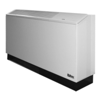
Electrical Connections
Air Coil
5.0"
Control Box
Escutcheon Plate
Compressor Cover
Wiring Diagram
Fan Motor Cover
(127mm)
9.0"
(229mm)
1.0"*
(25mm)
*1.0" (25mm) from inside
surface of wall
Electrical Conduit
Floor
Junction Box
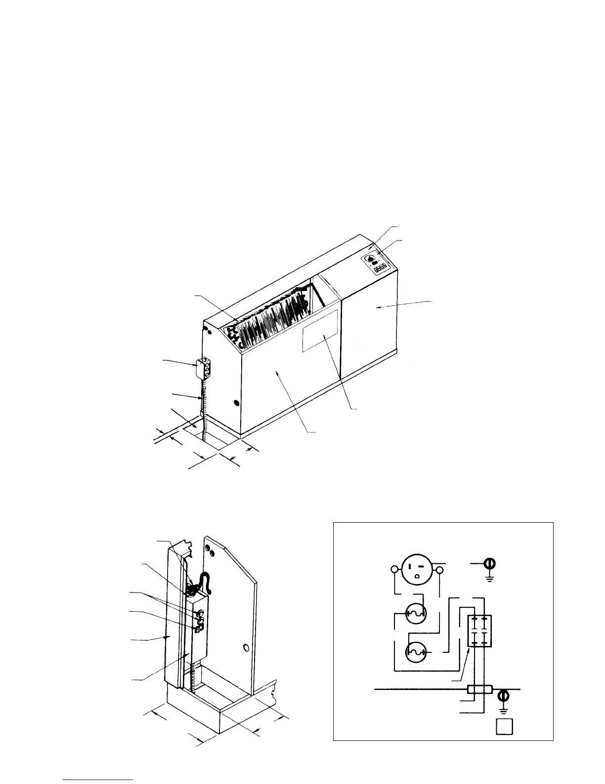
Figure 4. Cord & Plug Connection (Field Installed)
Power Cord
Receptacle Plug
Fuse Holder
Switch
Backwrap
Fuse
Disconnect Box
10.0"
(254mm)
5.00"
(127mm)
Figure 3. Standard electrical connection – Junction box
Standard Electrical Connection
Each chassis comes with a junction box mounted on the
side of the chassis and contains the field electrical connection.
Note: If electrical wiring or conduit comes through the
floor, all wires or conduit should be sealed at this point. It
will prevent any condensation or water leakage that may
occur due to lack of preventive maintenance. Each unit has
an internal condensate trap but will require cleaning.
Note: We suggest wiring coming through the wall should
also be sealed to stop cold air infiltration through the wall
cavity which could affect unit thermostat operation.
Remove the junction box cover, selecting the proper
knockout and remove it. Install a strain relief and pass the
wires through the strain relief into the junction box making
the connection and reinstall the junction box cover.
Note: Check the local code concerning correct electri-
cal connection.
Cord & plug electrical connection (field installed)
Cord connected equipment comes with a box and appropriate
voltage receptacle. However, a disconnect switch and fuses
can also be provided in the box. As an option, the box
comes factory mounted on the backwrap and is ready to be
field wired to the incoming power. The box is mounted on
the same side as the piping.
It is the responsibility of the installing contractor to make
the proper electrical connection to the electrical box, using
the same method as described in the standard electrical
connection. See Figures 3 and 4.
Cabinet Power Connection
(Field Installed)
Receptacle, Fuses & Disconnect Switch
(Requires plug cord on chassis.)
Fused Disconnect Box
Wire Diagram 61408101
WH or RD
BK
BK
Fuse
RECEPTACLE
GR/YE
PK
PK
Fuse
REV
0
Disconnect Switch
BK
WH
WH
 Loading...