IM-447 / Page 11
Valve
Valve
Pins-Female
Pins-Female
Plug (1) required
Plug (1) required
Water Flow
Use Upper
Knockout
Conduit, Fitting
Bushing
Conduit
Elbow
Water Tube Extension
Conduit, Fitting Bushing
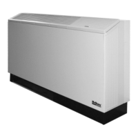
Motorized
Valve
Normally Open Valve
Normally Closed Valve
Motorized Valve & Relay for Unit Sizes 007 to 019
Wired as shown below the motorized valve will open on a call
for compressor operation. Valves for unit sizes 007 to 019 are
1
⁄2˝ power-open spring-return. Other thermostat combina-
tions may be used. Valve and auxiliary relay are purchased
separately.
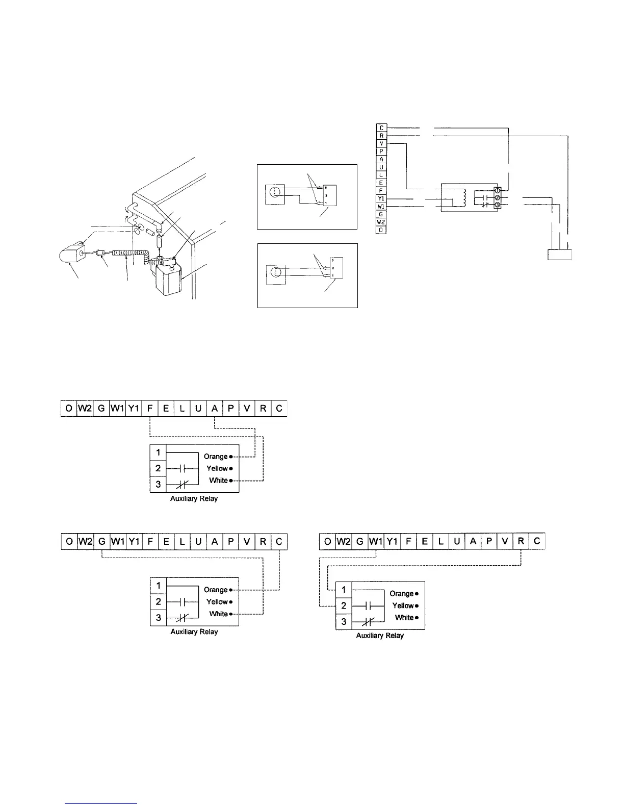
The auxiliary relay is designed to interface external equipment
with the Mark IV/AC board. The auxiliary relay has been pro-
vided with the components necessary to protect from electrical
damage that may occur to the Mark IV/AC board when using
standard off-the-self relays. The auxiliary relay can be used to
provide fault signals, unit operation signals, or to provide a
means for remote equipment to control the Mark IV/AC board.
The orange, yellow, and white connections are short flying leads
pre-attached to the board. The diagrams shown are some
connection examples.
Auxilliary Relay (P/N 106059701)
WSHP Mark IV/AC Board Low Voltage Terminal Strip
WSHP Mark IV/AC Board Low Voltage Terminal Strip
WSHP Mark IV/AC Board Low Voltage Terminal Strip
Operation: In this example
the auxiliary relay contacts
can be used to indicate a
fault condition. With the
auxiliary relay connected
as shown, the normally
open contacts will close
during a fault condition.
Operation: In this example
the auxiliary relay contacts
can be used to signal
WSHP fan operation to
another device. In this
example when the
thermostat energizes the
“G” terminal the auxiliary
relay normally open
contacts will close.
Operation: In this example
the auxiliary relay is used
to interface other control
devices to the Mark IV/AC
board. Using the Orange (-)
and White (+) wires, and
24vac or 24vdc, another
device could be used to
start and stop the WSHP
heating sequence.
Control Options on Mark IV/AC Units
Note: The wiring shown below can only be used when the “P”
terminal is not being used as a pump restart signal to other
equipment. If the “P” terminal must be used as a pump restart signal
to other equipment, then wire the auxiliary relay’s yellow wire to
“Y1”, white wire to “W1”, and orange wire to “C”, then the valve will
open on a call for occupied heating or cooling from the thermostat.
Motorized Valve Relay (P/N 859004354)
(P/N Valve N/O 106071401) (P/N Valve N/C 106071301)
Notes:
1. Use soft solder process on water tubing outside of chassis.
2. Route wires along with power leads.
3. Left hand installation shown - right hand installation is “mirror”
opposite.
4. Motorized valve (511) to be parallel to the end panel.
5. Copper to be washed prior to soldering.
6. Route conduit so it does not interfere with manual operation of
motorized valve.
WH
YE
OR
GN7
BL6
BL6
BL9
BL8
BL9
BL8
6 3 1
GN7
PC Board
Terminal Strip
Motorized Valve
Control Relay
Receptical
 Loading...