MC3419 3-Axis Accelerometer EV3419A Quick Start Guide and Demo
mCube Proprietary. APS-045-0033v1.0 6 / 20
© 2020 mCube Inc. All rights reserved.
2 ASSEMBLY AND TEST
Please note that the SPI and I2C interfaces cannot both be active at the same time as
the clock (SCK) and data (SDA) are shared between the two protocols.
2.1 I2C INTERFACE
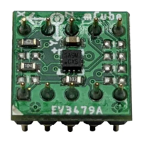
The EV3419A evaluation board can be easily wired to any microcontroller. This example
shows a typical Arduino DUE platform. For other microcontrollers, be sure it has I2C with
repeated-start support, then port the code. Please refer to the illustration below to connect the
related pins.
• Connect DVDD to the power supply, 3.3V. (WARNING: attempting to power the part at
a voltage exceeds the maximum rating of 3.6V is likely to damage it.)
• Connect GND to common power/data ground.
• Connect the SCL pin to the I2C clock SCL pin on your Arduino.
• Connect the SDA pin to the I2C data SDA pin on your Arduino.
The MC3419 has a default I2C address of 0x4C and it can be changed to 0x6C by tying
the SDO pin to VDD.