I
MDR-2000
V3
User's Reference Manual
Hardware
DB25 Pin
1
2
3
4
5
6
7
20
DB25 Pin
1
3
2
6
20
4
7
5
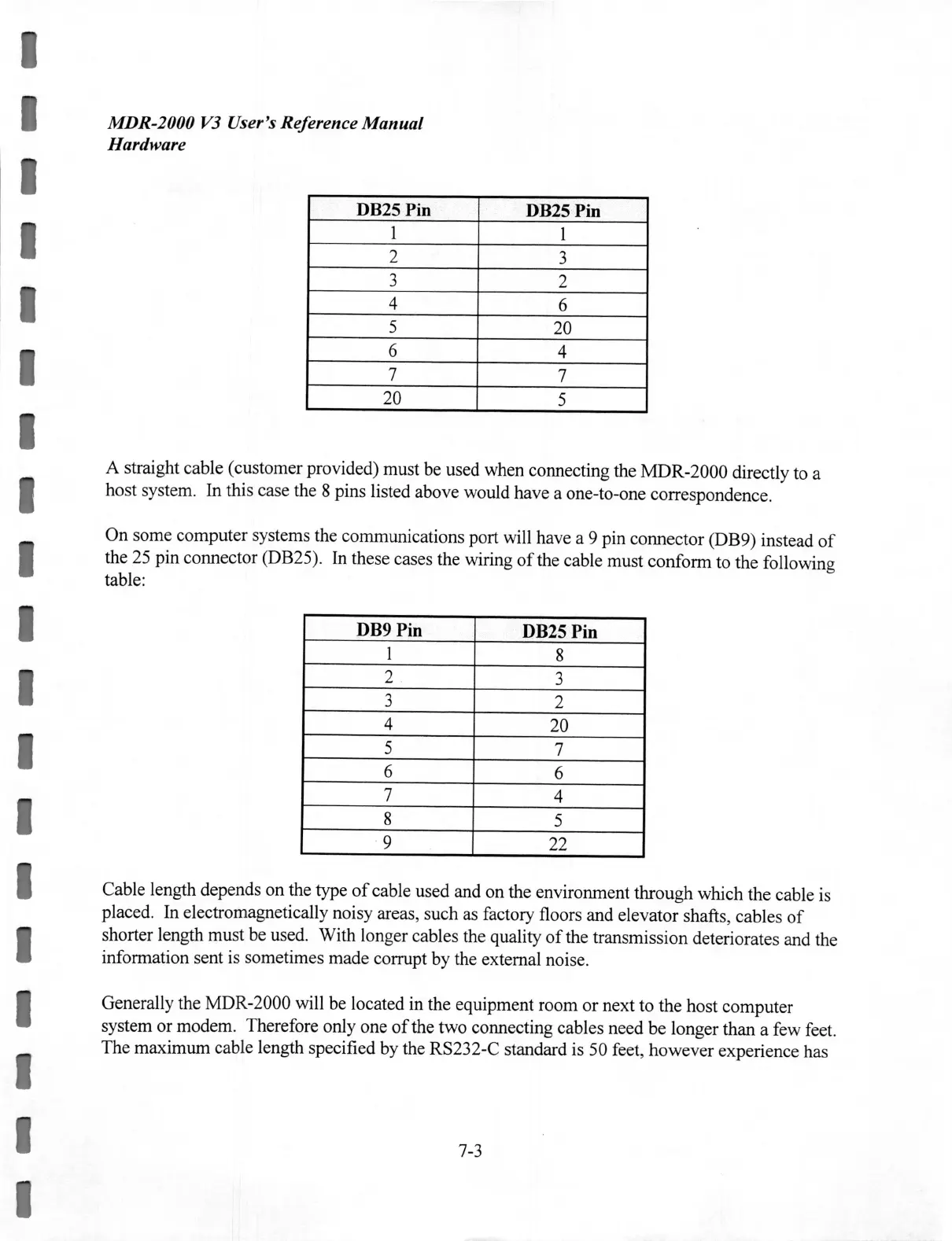
A straight cable (customer provided) must be used when connecting the MDR-2000 directly to a
host system. In this case the 8 pins listed above would have a one-to-one correspondence.
On some computer systems the communications port will have a 9 pin connector (DB9) instead
of
the 25 pin connector (DB25). In these cases the wiring
of
the cable must conform to the following
table:
DB9 Pin
DB25 Pin
1
8
2
3
3
2
4
20
5
7
6
6
7
4
8
5
9 22
Cable length depends on the type
of
cable used and on the environment through which the cable is
placed. In electromagnetically noisy areas, such as factory floors and elevator shafts, cables
of
shorter length must be used. With longer cables the quality
of
the transmission deteriorates and the
information sent is sometimes made corrupt by the external noise.
Generally the MDR-2000 will be located in the equipment room or next to the host computer
system or modem. Therefore only one
of
the two connecting cables need
be
longer than a few feet.
The maximum cable length specified by the RS232-C standard is 50 feet, however experience has
7-3
 Loading...